Download

1 / 16
160 likes | 282 Vues
This research focuses on effectively detecting recoil deuterons using silicon detectors without interfering with established experimental setups. It discusses optimal conditions for positioning the silicon detector 1 cm from the target and analyzes the impact on angular ranges and event detection. Highlighting the advantages of a Beth-Heitler process, the study addresses background noise from Moller electrons and protons, proposing adjustments to target distance and beam intensity for improved data collection. A comprehensive approach to measuring full phase distributions within specified limits is presented.

E N D
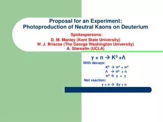
The Problem KIN2 q=19°.30 deuterium tmin=-0.123 GeV2 q’=2.78 GeVP’d=.352 Gev Inner calo 10x9 block R=13.5 cm qg’=8° tmin=-0.33 GeV2 q’=2.72 GeVP’d=.579 Gev How to detect the maximum of recoil deutons withreasonablesilicon detector Withoutinterferewith the acceptedexperiment PYB
Reasonnable silicona+/- 40° angular range ===> close of the Target as possible 2 cm 20° Move the beam it is possibleletsaid 1cm Detector close to 1cm from the target Silicon detector dimension +/- 2xtan(40°)/sin(18)=+/-5.42cm which is limit of reasonable This insure that all the dvcs events produced in the target and with -tmin <t<0.33GeV2 And with fg<90° or fg>270° are emitted in front of the silicon. PYB We favor the Beth-Heither process
D 18o f Q=k-k’ QgD TD MEV QgD PYB -t GeV2
LD2 a SILICON 2 Stop in Si DE>> MeV 3 Stop after Si DE<10 MeV 1 Stop in LD2 DE=0 2 2 DE=0 DE=0 3 3 1 1 T Mev cosa At angle a fixed At T fixed Note: With a Silicon thickness of 1mm (DE)2~5-10MeV . In the silicon of Compton Polarimeter (DE)3~0.3 MeV PYB
Conclusion: it is possible to do a full f distribution between -80o to+80o f for the bin [2.6,3.] GeV2 in –t . in this bin DE is >3MeV 10 times bigger that in the Compton Polarimeter PYB
Siliconstrips: 1mm 2 cm 100 mm 16x(5.5x50 mm2) strips PYB 32 strips
Using ARS allow: Times coincidence ~ 1-2 ns DE analyze Vacuum feed-through Like this of the polarimeter Compton ARS ARS Charge amplifier . + derivation Only the charge amplifier require a new study PYB
Proton from the electro-desintegration of the deuton e+De+n+p • Moller electrons Are the two dominant backgrounds The proton field was computed by Pavel:
15 cm LH2 I=10mA 32 stripes : 5,5 x100 mm2 at 2 cm from the beam But some stop in the deuterium Tp< 21 MeV PYB
Electron Backgroung: 2 cm Tan(a)=d/l=2/16 a=7.12° The forward part of the silicon must have difficulties. If it the case 1,2 or n strips can be forgotten The best will be to use a shorter target 5 or 4 cm a= 18o But that will implied to increase beam intensity to 20 µA and this intensity require the use of the raster !!!!!! PYB
Possible Improvement 20 o Target f=20 mm
An other setup 18o D=8cm 0 X
But an any case the absorption in the LH2 will conduct at the same range in t and f
My feeling: • It is technically doable* for KIN2 • It will be better to used a 4 or 5 cm target !! • The range in t and f is limited . • In this range a cross section can be extract • In this range the B-H is dominant * • mechanical support of the silicon • vacuum feed –through • position of target versus beam • Preamplifier “Le jeu en vautil la chandelle ?” Knowing that this technique will be and more difficult to be applied at the 12 GeV when Q2 and twill increase. PYB