Syllabus and slides
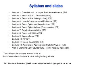
Syllabus and slides. Lecture 1: Overview and history of Particle accelerators (EW) Lecture 2: Beam optics I (transverse) (EW) Lecture 3: Beam optics II (longitudinal) (EW) Lecture 4: Liouville's theorem and Emittance (RB) Lecture 5: Beam Optics and Imperfections (RB)

Syllabus and slides
E N D
Presentation Transcript
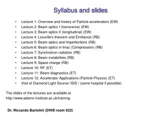
Syllabus and slides Lecture 1: Overview and history of Particle accelerators (EW) Lecture 2: Beam optics I (transverse) (EW) Lecture 3: Beam optics II (longitudinal) (EW) Lecture 4: Liouville's theorem and Emittance (RB) Lecture 5: Beam Optics and Imperfections (RB) Lecture 6: Beam Optics in linac (Compression) (RB) Lecture 7: Synchrotron radiation (RB) Lecture 8: Beam instabilities (RB) Lecture 9: Space charge (RB) Lecture 10: RF (ET) Lecture 11: Beam diagnostics (ET) Lecture 12: Accelerator Applications (Particle Physics) (ET) Visit of Diamond Light Source/ ISIS / (some hospital if possible) The slides of the lectures are available at http://www.adams-institute.ac.uk/training/undergraduate Dr. Riccardo Bartolini (DWB room 622) r.bartolini1@physics.ox.ac.uk
Lecture 10 Synchrotron radiation properties of synchrotron radiation synchrotron light sources Lienard-Wiechert potentials Angular distribution of power radiated by accelerated particles Angular and frequency distribution of energy radiated: Radiation from undulators and wigglers
What is synchrotron radiation The electromagnetic radiation emitted when the charged particles are accelerated radially (v a) is called synchrotron radiation It is produced in the synchrotron radiation sources using bending magnets undulators and wigglers Electromagnetic radiation is emitted by charged particles when accelerated
Broad Spectrum which covers from microwaves to hard X-rays: the user can select the wavelength required for experiment; synchrotron light Synchrotron radiation sources properties High Flux: high intensity photon beam, allows rapid experiments or use of weakly scattering crystals; High Brilliance (Spectral Brightness): highly collimated photon beam generated by a small divergence and small size source (partial coherence); High Stability: submicron source stability Polarisation: both linear and circular (with IDs) Pulsed Time Structure: pulsed length down to tens of picoseconds allows the resolution of process on the same time scale Flux = Photons / ( s BW) Brilliance = Photons / ( s mm2 mrad2 BW )
A brief history of storage ring synchrotron radiation sources • First observation: • 1947, General Electric, 70 MeV synchrotron • First user experiments: • 1956, Cornell, 320 MeV synchrotron • 1st generation light sources: machine built for High Energy Physics or other purposes used parasitically for synchrotron radiation • 2nd generation light sources: purpose built synchrotron light sources, SRS at Daresbury was the first dedicated machine (1981 – 2008) • 3rd generation light sources: optimised for high brilliance with low emittance and Insertion Devices; ESRF, Diamond, … • 4th generation light sources: photoinjectors LINAC based Free Electron Laser sources; FLASH (DESY), LCLS (SLAC), …
X-ray tube 60W bulb Candle diamond X-rays from Diamond will be 1012 times brighter than from an X-ray tube, 105 times brighter than the SRS ! Peak Brilliance
Electrons are generated and accelerated in a linac, further accelerated to the required energy in a booster and injected and stored in the storage ring Layout of a synchrotron radiation source (I) The circulating electrons emit an intense beam of synchrotron radiation which is sent down the beamline
Main components of a storage ring Insertion devices (undulators) to generate high brilliance radiation Insertion devices (wiggler) to reach high photon energies
photo-emission (electrons) electronic structure & imaging EXAFS XRF imaging fluorescence Many ways to use x-rays crystallography & imaging diffraction scattering SAXS & imaging absorption Spectroscopy EXAFS XANES & imaging from the synchrotron to the detector
3rd generation storage ring light sources ESRF SSRF 1992ESRF, France (EU) 6 GeV ALS, US 1.5-1.9 GeV 1993 TLS, Taiwan 1.5 GeV 1994ELETTRA, Italy 2.4 GeV PLS, Korea 2 GeV MAX II, Sweden 1.5 GeV 1996APS, US 7 GeV LNLS, Brazil 1.35 GeV 1997 Spring-8, Japan 8 GeV 1998BESSY II, Germany 1.9 GeV 2000ANKA, Germany 2.5 GeV SLS, Switzerland 2.4 GeV 2004SPEAR3, US 3 GeV CLS, Canada 2.9 GeV 2006: SOLEIL, France 2.8 GeV DIAMOND, UK 3 GeV ASP, Australia 3 GeV MAX III, Sweden 700 MeV Indus-II, India 2.5 GeV 2008SSRF, China3.4 GeV 2009PETRA-III, D 6 GeV 2011ALBA, E 3 GeV 11/30
Oct 2006 Diamond Aerial views June 2003
Synchrotron radiation is emitted in an arc of circumference with radius , Angle of emission of radiation is 1/ (relativistic argument), therefore transit time in the arc of dipole Heuristic approach to synchrotron radiation During this time the electron travels a distance The time duration of the radiation pulse seen by the observer is the difference between the time of emission of the photons and the time travelled by the electron in the arc The width of the Fourier transform of the pulse is
Lienard-Wiechert Potentials (I) with the current and charge densities of a single charged particle, i.e. have as solution the Lienard-Wiechert potentials The equations for vector potential and scalar potential [ ]ret means computed at time t’
Lineard-Wiechert Potentials (II) and are called Lineard-Wiechert fields velocity field acceleration field The electric and magnetic fields generated by the moving charge are computed from the potentials Power radiated by a particle on a surface is the flux of the Poynting vector Angular distribution of radiated power [see Jackson] radiation emitted by the particle
and substituting the acceleration field [Jackson] velocity acceleration: synchrotron radiation Assuming cone aperture 1/ When the electron velocity approaches the speed of light the emission pattern is sharply collimated forward
Integrating over the whole solid angle we obtain the total instantaneous power radiated by one electron (Larmor formula and its relativistic generalisation) Total radiated power via synchrotron radiation • Strong dependence 1/m4 on the rest mass • proportional to 1/2 ( is the bending radius) • proportional to B2 (B is the magnetic field of the bending dipole) The radiation power emitted by an electron beam in a storage ring is very high. The surface of the vacuum chamber hit by synchrotron radiation must be cooled.
In the time Tb spent in the bendings the particle loses the energy U0 Energy loss via synchrotron radiation emission in a storage ring i.e. Energy Loss per turn (per electron) Power radiated by a beam of average current Ib: this power loss has to be compensated by the RF system Power radiated by a beam of average current Ib in a dipole of length L (energy loss per second)
The radiation integral (I) Angular and frequency distribution of the energy received by an observer The energy received by an observer (per unit solid angle at the source) is Using the Fourier Transform we move to the frequency space Neglecting the velocity fields and assuming the observer in the far field: n constant, R constant Radiation Integral 19/30
The radiation integral (II) The radiation integral can be simplified to [see Jackson] How to solve it? • determine the particle motion • compute the cross products and the phase factor • integrate each component and take the vector square modulus Calculations are generally quite lengthy: even for simple cases as for the radiation emitted by an electron in a bending magnet they require Airy integrals or the modified Bessel functions (available in MATLAB) 20/30
Radiation integral for synchrotron radiation Trajectory of the arc of circumference [see Jackson] In the limit of small angles we compute Substituting into the radiation integral and introducing 21/30
Using the properties of the modified Bessel function we observe that the radiation intensity is negligible for >> 1 Critical frequency and critical angle Higher frequencies have smaller critical angle Critical frequency Critical angle For frequencies much larger than the critical frequency and angles much larger than the critical angle the synchrotron radiation emission is negligible
It is possible to verify that the integral over the frequencies agrees with the previous expression for the total power radiated [Hubner] Frequency distribution of radiated energy The frequency integral extended up to the critical frequency contains half of the total energy radiated, the peak occurs approximately at 0.3c It is also convenient to define the critical photon energy as For electrons, the critical energy in practical units reads 50% 50%
Dependence of the frequency distribution of the energy radiated via synchrotron emission on the electron beam energy Critical frequency Synchrotron radiation emission as a function of beam the energy Critical angle No dependence on the energy at longer wavelengths Critical energy for electrons! How does this change for protons?
Brilliance with IDs (medium energy light sources) Brilliance dependence with current with energy with emittance Medium energy storage rings with in-vacuum undulators operated at low gaps (e.g. 5-7 mm) can reach 10 keV with a brilliance of 1020 ph/s/0.1%BW/mm2/mrad2 25/30
Polarisation in the orbit plane Polarisation orthogonal to the orbit plane Polarisation of synchrotron radiation In the orbit plane = 0, the polarisation is purely horizontal Integrating on all frequencies we get the angular distribution of the energy radiated Integrating on all the angles we get a polarization on the plan of the orbit 7 times larger than on the plan perpendicular to the orbit
Undulators and wigglers Periodic array of magnetic poles providing a sinusoidal magnetic field on axis: Insertion devices (undulators) to generate high brilliance radiation Constructive interference of radiation emitted by different electrons at different poles 27/30
Continuous spectrum characterized by ec = critical energy ec(keV) = 0.665 B(T)E2(GeV) eg: for B = 1.4T E = 3GeV ec = 8.4 keV (bending magnet fields are usually lower ~ 1 – 1.5T) bending magnet - a “sweeping searchlight” Synchrotron radiation from undulators and wigglers wiggler - incoherent superposition K > 1 Quasi-monochromatic spectrum with peaks at lower energy than a wiggler undulator - coherent interference K < 1
Summary Accelerated charged particles emit electromagnetic radiation Synchrotron radiation is stronger for light particles and is emitted by bending magnets in a narrow cone within a critical frequency Undulators and wigglers enhance the synchrotron radiation emission Synchrotron radiation has unique characteristics and many applications
Bibliography J. D. Jackson, Classical Electrodynamics, John Wiley & sons. E. Wilson, An Introduction to Particle Accelerators, OUP, (2001) M. Sands, SLAC-121, (1970) R. P. Walker, CAS CERN 94-01 and CAS CERN 98-04 K. Hubner, CAS CERN 90-03 J. Schwinger, Phys. Rev. 75, pg. 1912, (1949) B. M. Kincaid, Jour. Appl. Phys., 48, pp. 2684, (1977).