Download
1 / 21
220 likes | 253 Vues
Explore the cutting-edge magnetic instrumentation developments at Imperial College, featuring vector DC magnetometers with highly accurate three-axis fluxgate design, fluxgate analogue control electronics, digital implementation, and anisotropic magnetoresistance effects.

E N D
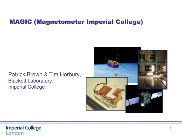
MAGIC (Magnetometer Imperial College) Patrick Brown & Tim Horbury, Blackett Laboratory, Imperial College 1
Heritage: • Vector DC Magnetometers (0 - 10Hz) • Highly accurate three axis fluxgate design • Mass optimised two core implementation • Dual sense and feedback windings • Offset stability < 0.05 nT/°C • Noise density < 8pT/root Hz @1Hz • Accuracy – Better than 0.1nT • Missions: Cluster, Cassini, Double Star • Limitations • Accuracy dependent on core size, power, • Resource overhead • Mass 200g, Power ~0.4W, Magnetic Cleanliness • Current space plasma S/C use two fluxgates on long boom • Alternative sensing technology needed for very small sats Double Star Magnetometer 2
Fluxgate Analogue Control Electronics Benefits include improved linearity and temperature stability. Scale factor depends only on feedback resistor/gain stage and coil constant. Considerable effort spent minimising even harmonics in drive signal. Some odd harmonics due to transformer effect. Includes anti-aliasing filter 3
Fluxgate: Offset and Noise Density • Noise density stable <5pT/Rt(Hz) across -60oC to +30oC • Offset stability <0.05nT/oC Carr et al. 2005 Sensor offset recently tested down to -150oC with noise floor of <20pT/Rt(Hz) 4 4
Fluxgate: Digital Implementation (O’Brien et al 2007) • <30pT/√Hz at 1Hz • Digital control loop at TRL4 • Baseline design for Solar Orbiter • Currently studying migrated to rad-hard mixed signal ASIC • Current design: Noise level <10pT/√Hz at 1Hz 5
Anisotropic Magnetoresistance Magneto Resistance Effect Change of resistance in magnetic field AMR single layer permalloy, AMR ΔR/Rmin of order 1- 2% Barber Poles Max, sensitivity & linearity at M v H 45o Conductive strips for linear operation AMR Sensors Thin film solid state devices Mass <1g Implemented as Wheatstone bridge Sensitivity varies with bridge voltage, VB Picture Courtesy Philips
Integrated coils • Set - Reset Coils • On chip coil parallel to easy axis • Used to re-align the anisotropic direction • Large current spike needed • Clocked pulsing known as ‘flipping’ • Can be used to extract sensor offset • Requires de-modulation to DC • Improves sensor noise floor • Offset coils • On chip coil parallel to field sensitive axis • Used in closed loop back off measured field • Improves linearity of device • Both Offset and Set – Reset used in low field ( < 1000nT) operation
Some recent results Stutzke et al Zimmermann et al AMR Noise Floor 100pT/Rt(Hz) AMR Noise Floor 24pT/Rt(Hz) 8 8
Magnetoresistive magnetometer 3axis Fluxgate Single axis MR • Control loop will be compatible with Digimag ASIC • Hybrid 3 axis sensor as a single chip planned for late 2010 • MAGIC Breadboard currently single axis CINEMA OB Triaxial sensor 9
Stimulus measurement – Fluxgate vs AMR • FGM and AMR in 3Hz 6nT ptp stim field AMR Fluxgate 10
MAGIC Noise Magnetometer time series Magnetometer PSD overlaid with simulated ULF wave on ground 11
MR DSP FGM Effect of flipping MR flipping at 1kHz.Drift much worse without flipping
Test results on most recent design Motivation: To get reduced drift and science mode power saving of up to 0.4W . Very encouraging result. Next - Test again over LEO field ranges and across temperature range Full Three axis calibration before end of 2009 .
Imperial Test & Calibration Facilities CALIBRATION Facility (Staffordshire UK) Three axis Helmholtz design Dynamic Field Compensation Will determine Gains, Misalignments, Linearity MOBILE Coil Facility (Currently at Astrium, Friedrichshafen) Two axis Helmholtz design Magnetometer Array and rotation table Under PC Control with Multi-Dipole Model fitting Use: Measurement of magnetic moment Potential use on a CubeSat 3axis Helmholtz calibration coil facility Mobile coil facility to measure magnetic moments 15
Moonlite Impact Trial – May 2008 • Location • MOD Rocket Track at Pendine, Wales • Purpose of trial • Demonstrate survivability of shell & payload • Determine internal acceleration environment • Assess alternate packing regimes (potting, glass spheres) • Test Set up • Accelerated to 40g to 300ms-1 for 0.9sec
Magnetometer • Impact Data • Only sensors flown in axial and vertical orientations • Compartment potted after assembly • Magnetometer tested before and after firing and no change in performance Flow holes
MoonLITE (Light weight Interior andTele-coms Experiment) UK Mission to the moon – Phase A 2010 Mission Goal Instrumentation on the moon by 2014 Two mission elements An orbiter deployment and relay spacecraft 100kmx40km elliptical polar orbit Four instrumented penetrators Target Regions Near side, far side and at the poles Shadowed craters a priority Mission lifetime Orbiter – 1.5 years Penetrators – 1 year Releases over 2 months
Trial Payload Mass spectrometer Radiation sensor Batteries Magnetometers Accelerometers Power Interconnection Processing Micro-seismometers Accelerometers, Thermometer Batteries,Data logger Drill assembly
Trial Test Results • Max deceleration load 11kG max on-axis • ~10kG on vertical axis • Magnetometer survived OK • Further penetrators trials targeted at Ganymede very likely to be funded by ESA • Next trial plan to include magnetometer electronics and be powered during firing Smith et al, 2008