Download
1 / 18
310 likes | 1.73k Vues
Analysis of Beams in Bending (5.1-5.3). MAE 314 – Solid Mechanics Yun Jing. Bending Moment Along a Beam. In this chapter, we will learn how to find the bending moment M along the beam. M is not necessarily constant; sometimes M is a function of x.

E N D
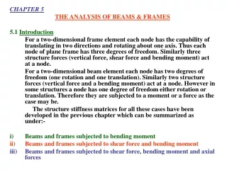
Analysis of Beams in Bending(5.1-5.3) MAE 314 – Solid Mechanics Yun Jing Analysis of Beams in Bending
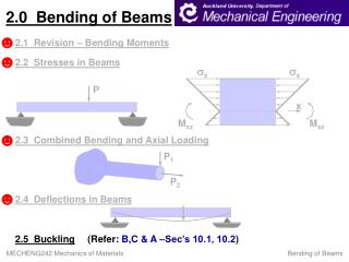
Bending Moment Along a Beam • In this chapter, we will learn how to find the bending moment M along the beam. • M is not necessarily constant; sometimes M is a function of x. • We will also solve for the shear force V(x), which will be used in Chapter 6. • As before, we need a new FBD every time the loading changes. 2 1 3 1 2 Analysis of Beams in Bending
Review of Beam Supports • 3 equilibrium equations: Σ FY = 0, Σ FX = 0, Σ M = 0 • Ignore the horizontal (x-direction) components, because these are axial loading. R1 R3 R1 R3 R1 M1 R2 R2 R2 R1 M1 R1 R3 M2 M1 R1 R3 R3 R4 R2 R2 R4 R2 Analysis of Beams in Bending
Sign Convention • Recall the applied loading results in both a bending moment M and a shear force V. Positive shear and bending moment Analysis of Beams in Bending
Example Problem Draw the shear and bending moment diagrams for the beam and loading shown, and determine the maximum absolute value (a) of the shear and (b) of the bending moment. Analysis of Beams in Bending
Relations Between F, V, and M • For beams with more complicated loading, it is helpful to develop a relationship between load, shear and bending moment. • Sum forces in the vertical direction. or Analysis of Beams in Bending
Relations Between F, V, and M • Sum moment about C’. • Neglect (Δx)2 term since it is much smaller thanΔx term. or Analysis of Beams in Bending
Example Problem Determine (a) the equations of the shear and bending moment curves for the beam and loading shown, and (b) the maximum absolute value of the bending moment in the beam. Analysis of Beams in Bending
Example Problem Draw the shear and bending-moment diagrams for the beam and loading shown. Analysis of Beams in Bending
Design of Beams in Bending(5.4) MAE 314 – Solid Mechanics Yun Jing Design of Beams in Bending
Design of Beams for Bending • Recall the largest normal stress in the beam subject to bending occurs at the surface and can be defined as • A safe design requires the maximum stress is no more than the allowable stress (σmax ≤ σall), so where Design of Beams in Bending
Procedure for Design • Determine the value for σall. • Draw shear and moment diagrams. • From the diagrams, determine the maximum absolute bending moment. • Determine the minimum allowable value Smin. • Use Smin to determine best cross section dimensions. • Timber beam: Smin = bh2/6 • Rolled-steel beam: Use Appendix C in textbook Design of Beams in Bending
Example Problem For the beam and loading shown, design the cross section of the beam, knowing that the grade of timber used has an allowable normal stress of 12 MPa. Design of Beams in Bending
Example Problem Knowing that the allowable stress for the steel used is 160 MPa, select the most economical S-shape beam to support the loading shown. Design of Beams in Bending
Example Problem • A beam is to be made of steel that has an allowable bending stress of 170MPa. Select an appropriate W shape that will carry the loading shown in the figure below Design of Beams in Bending