Download
1 / 11
600 likes | 4.12k Vues
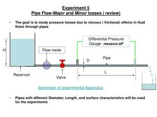
H. Reservoir. Experiment 5 Pipe Flow-Major and Minor losses ( review). The goal is to study pressure losses due to viscous ( frictional) effects in fluid flows through pipes. Differential Pressure Gauge- measure Δ P. Flow meter. Pipe. D. L. Valve. Schematic of experimental Apparatus.

E N D
H Reservoir Experiment 5Pipe Flow-Major and Minor losses ( review) • The goal is to study pressure losses due to viscous ( frictional) effects in fluid flows through pipes Differential Pressure Gauge- measure ΔP Flow meter Pipe D L Valve Schematic of experimental Apparatus • Pipes with different Diameter, Length, and surface characteristics will be used for the experiments
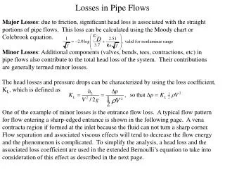
Major and Minor losses Total Head Loss( hLT) = Major Loss(hL)+Minor Loss (hLM) Due to sudden expansion, contraction, fittings etc Due to wall friction In this experiment you will find friction factor for various pipes K is loss coefficient must be determined for each situation For Short pipes with multiple fittings, the minor losses are no longer “minor”!!
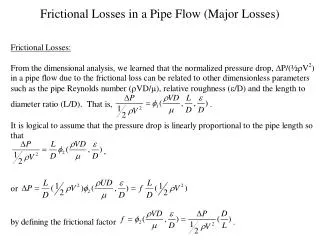
Major loss Differential Pressure Gauge- measure ΔP • Physical problem is to relate pressure drop to fluid parameters and pipe geometry L ρμε V Pipe D Using dimensional analysis we can show that
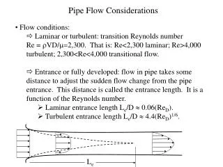
Friction Factor • For Laminar flow ( Re<2300) inside a horizontal pipe, friction factor is independent of the surface roughness. For Laminar flow • For Turbulent flow ( Re>4000) it is not possible to derive analytical expressions. • Empirical expressions relating friction factor, Reynolds number and relative roughness are available in literature
Friction factor correlations f is not related explicitly Re and relative roughness in this equation. The following equation can be used instead
Moody’s chart for friction factor f Increases Laminar f=64/Re Smooth Transition ReD
Minor Losses • Flow separation and associated viscous effects will tend to decrease the flow energy and hence the losses • The phenomenon is fairly complicated. Loss coefficient ‘K’ will take care of this complicities Valves Bends T joints Expansions Contractions
Digital Manometer To measure ΔP Reservoir H Experiment 5 - New Experimental Set up
Reservoir H L1 L2 L3 L4 Δx3 Δx1 Δx2 Experiment 5 - Experimental Steps & Details • Overall Measurements • Measure the Reservoir Height, H • Measure the Distances L1, L2, etc. • Measure the distances Δx1, Δx2, etc. Measure the pipe diameters • For EACH PIPE Follow Steps below • Set the reservoir height, H, to the maximum level, approx. close to the ‘spill-over’ partition height. Record the level. • Adjust the flow rate to a relatively high value, wait for steady flow to be established. • Measure the flow rate. • Measure the pressure drop, ΔP, for this flow rate. • Reduce the flow rate, by using the valves, repeat steps 1 & 2. • Reduce the reservoir height and repeat steps 1-3. • Repeat all steps until 3 reservoir heights have been measured • Hence for each pipe, you will measure ΔP, for six flow rates • (3 H x 2 valve openings) Δx2