Download
1 / 20
200 likes | 352 Vues
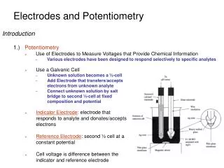
Micro Pixel Chamber ( μ -PIC) with resistive electrodes for spark reduction. Atsuhiko Ochi Kobe University. 2/7/2013 3 rd International MPGD conference. Outline. Design of the detector Performance of spark reduction Operation mode without AC coupling Remaining problems to be solved

E N D
Micro Pixel Chamber (μ-PIC) with resistive electrodes for spark reduction Atsuhiko Ochi Kobe University 2/7/2013 3rd International MPGD conference
Outline • Design of the detector • Performance of spark reduction • Operation mode without AC coupling • Remaining problems to be solved • Conclusion A. Ochi, MPGD2013 conference
Properties of the μ-PIC Drift plane • Fine position/timing resolution, high rate capability, … those basic properties are same as other type of MPGDs. • It has no floating structures (wire, foil, mesh…). • It is important properties for making seamless large detector. • Almost all production processes are commercially available. (PCB / FPC production process ) • More stabilities and robustness is needed for high ionized particle (HIP) • The electron density may excess the Raether limit (107-8) • To avoid the destruction of the electrodes due to spark, μ-PIC with resistive electrodes has been designed. • The resistive u-PIC design allow us to read all signal without AC coupling Cathode 400 μm Anode 400 μm Requirements for more stability 50 μm 100 μm A. Ochi, MPGD2013 conference
m-PIC with resistive cathode and capacitive readout Drift plane • Detector design • All cathodes are made from carbon-polyimide • Pickup electrodes are lied under cathodes and insulator • We have two dimensional signals Resistive cathode(-HV) 400 μm Anode Thin substrate Cathode (pickup) 300mV 50 μm Anode • Cathode signal on oscilloscope is inverted • Two dimensional signal is inducedon opposite sign. • Not charge shareing. Va = 660V, Gain ~ 20000 Pickup electrode Thick substrate A. Ochi, MPGD2013 conference
Process for manufacturing (g) Polishing the surface (h) Plating the anode pin (i) Etching the metal layer (j) Adhering the thick layer (k) Laser drilling for anode pin (l) Plating anode pin Start from double sided kapton (b) Thick plating on surface (~ 50μm) (c) Exposure using double side mask (d) Developing resist (e) Etching for the pattern (f) Fill the resistive polyimide & cure
Micro scope picture of a prototype (RC27) • Delivered at July 2012 • Very good accuracy (compared with previous samples) • Surface resistivity • About 50MW / strip (10cm) A. Ochi, MPGD2013 conference
Outline • Design of the detector • Performance of spark reduction • Operation mode without AC coupling • Remaining problems to be solved • Conclusion A. Ochi, MPGD2013 conference
Gain curve • Conditions • Drift field = 3.3kV/cm • 55Fe (5.9keV) • Using the signal from cathode pickup electrodes • Results • High gain (>60000) was achieved, and operation was stable (in case of Ar:C2H6=7:3) • There found small discharges over the maximum gain in right figure. However, no big sparks have been found around maximum gain. Gain Anode voltage [V] A. Ochi, MPGD2013 conference
Spark test using fast neutron • A few MeV – few tenth MeV neutron will produce recoiled nucleon inside detectors • That produce great amount of energy deposit (a few MeV/mm2) in gaseous volume. • The concerned problem for gas detector • “Raether limit” … the electron cluster more than 107-8 cause the detector to discharge. • We can evaluate the spark probability for HIP by measuring the spark rate dependencies on neutron irradiation • Neutron source • Tandem nucleon accelerator (3MeV deuteron) + Beryllium target.(Kobe University, Maritime dept.) • d+ 9Be n + 10B • Neutron energy: mainly 2MeV A. Ochi, MPGD2013 conference
neutron Spark probability measurements -HV (~1kV) Drift • HV current on anodes are monitoredwhile neutrons are irradiated • We found strong spark reduction using resistive cathode !! Cathode = 0V Anode +HV (~600V) Voltage recorder A [mA] 10 8 6 4 2 0 [mA] 10 8 6 4 2 0 Normalm-PIC (metal cathodes) Gain = 15000 Irradiation: 2.4×10³ neutron/sec Resistive cathode m-PIC Gain = 15000 irradiation: 1.9×10⁶ neutron/sec A. Ochi, MPGD2013 conference
Spark probability for fast neutron (~2MeV) • Conditions • Gas: Ar+C2H6(7:3) • Drift field:3.3kV/cm • Definition of the sparks: • Current monitor of HV module shows more than 2mA or 0.5mA. • Spark probability = [Spark counts] / neutron • The spark rates on normal m-PIC are are also plotted as comparison (cyan, magenta plots). • Results • Reduction of sparks are obviously found. The rate was 103-5 times less than normal m-PIC case at same gas gain. Spark reduction A. Ochi, MPGD2013 conference
Outline • Design of the detector • Performance of spark reduction • Operation mode without AC coupling • Remaining problems to be solved • Conclusion A. Ochi, MPGD2013 conference
Novel Operation condition with applying HV to resistive cathode (0V) Previous operation • Potential of electrodes: • Cathodes (resistive): 0V Negative HV • Anodes : Positive HV 0V • No HV on anodes • AC coupling capacitors and HV resistors are not needed +HV(~600V) R -HV(~-600V) New operation Direct connection to readout A. Ochi, MPGD2013 conference
Electron drift line for both operations Maxwell 3D + Garfield simulation Anode = +620V 印加 Cathode=-580V There is no significant difference A. Ochi, MPGD2013 conference
Operation test resultsGain curve and spark proberbility • Operation gas … Ar:C2H6=7:3 • Gain curve using 55Fe • A little bit higher operation ( ~ +10%) voltage is needed. • However, maximum attained gain is almost same. • Spark probability under fast neutron • Almost same in both mode. Spark probability under fast (~2MeV) neutron irradiation Gain curve using 55Fe Maximum gain is almost same A. Ochi, MPGD2013 conference
Outline • Design of the detector • Performance of spark reduction • Operation mode without AC coupling • Remaining problems to be solved • Conclusion A. Ochi, MPGD2013 conference
Operation test resultsGas gain variation • 55Fe (5.9keV) is irradiated • At the beginning, gain is about 8000. • The gain is growing up to 25000 in same operation voltage. • After irradiation of 2×10⁷counts/cm2 , the gain is stable at maximum. • It is thought that the gain variation is caused from charging up effect. A. Ochi, MPGD2013 conference
Remaining problem -- withstand HV of substrate -- • We have check three prototypes, and two of them are broken when HV applying. • Breakdowns are occurred between resistive cathode and pickup electrodes. • This point is inside the substrate. • Electric field simulation (using Maxwell 3D) • The substrate thickness is 25μm polyimide. • The withstand voltage of polyimide is around 300kV/mm • By the simulation of the electric field, there is extreme high electric field at the edge of resistive cathode and of pickup electrodes. • In the simulation, it is reached at 200kV/mm in our conditions. There is a slight margin. • Now we are making thicker substrate (37 μm) as a next sample. Edge of resistive cathode Edge of pickup electrodes A. Ochi, MPGD2013 conference
Future prospects Liftoff process with sputtering Photo resist (reverse pattern of surface strips) • Material of resistive electrodesPolyimide with carbon black Sputtered carbon • Fine patterning is available • No need to cure (high temperature) process • Large size production is available • Principle operation test has been done • Using sputtered carbon as resistive anode on MicroMEGAS • Details will be shown on Poster, and RD51 meeting. Substrate (polyimide) Metal/Carbon sputtering Substrate (polyimide) Developing the resists Substrate (polyimide) A. Ochi, MPGD2013 conference
Conclusion • m-PIC with resistive cathodes and capacitive readout is developed and tested. • More than 60000 of gas gain is achieved stably using 55Fe source under Ar(70%)+ethane(30%) gas. • Sparks are reduced strongly. • The spark rate under fast neutron (2MeV) is suppressed 105 times smaller than that of normal m-PIC. • Using capacitive readout, two-dimensional readouts without AC coupling are realized, and tested. • More improvement of the production is needed. • Substrate should hold high tolerance for high electric field. • New production method will improve the quality of the detector • These researches are supported by • Japan MPGD Basic R&D Team. • Grant-in-Aid for Scientific Research (No.23340072) • RD51 collaboration A. Ochi, MPGD2013 conference