Failure of composites
1.47k likes | 4.39k Vues
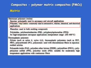
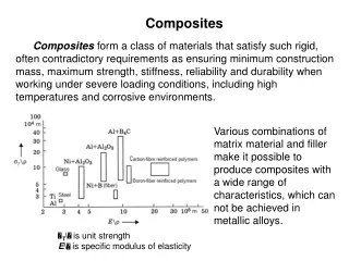
Failure of composites. John Summerscales. Outline of lecture. Strength Failure mechanisms Fractography Failure criteria Fracture mechanics. Strength. strength = stress at failure failure may be yielding in metals non-recoverable loss of elastic response first-ply failure

Failure of composites
E N D
Presentation Transcript
Failure of composites John Summerscales
Outline of lecture Strength Failure mechanisms Fractography Failure criteria Fracture mechanics
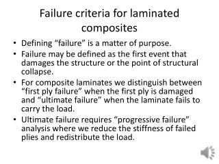
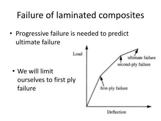
Strength • strength = stress at failure • failure may be • yielding in metals • non-recoverable loss of elastic response • first-ply failure • ultimate failure • one material can have several different strengths
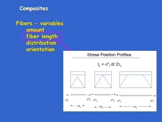
Strength • Kelly-Tyson equation for UD composites: • σc = σfVf + σm*(1-Vf) at high Vf, or • σc < σm#(1-Vf) at low Vf • where σm* is the tensile stress in the matrixat the failure strain of the fibre, and • σm# is the maximum tensile strength of the matrix • For small mis-alignments: • σc = σfVf / cos2θ = σfVfsec2θ
Failure mechanisms • matrix cracking • fibre fracture • debonding = interface failure • delamination = interlayer failure • fibre pullout • micro-buckling • kink bands • cone of fracture
Failure strain of composites • The key criterion for composite failure is the local strain to failure: ε’ a.k.a. elongation at breakand not stress • Note that ε’ for the fibre/matrix interfacei.e. transverse fibres = ~0.25 %
Matrix cracking maxmin • polyester resin ε’ = 0.9-4.0 % • vinyl ester ε’ = 1.0-4.0 % • epoxy resin ε’ = 1.0-3.5 % • phenolic resin ε’ = 0.5-1.0 % • data from NL Hancox, Fibre Composite Hybrid Materials, Elsevier, 1981.
Fibre fracture • S/R-glass ε’ = 4.6-5.2 % …. • E-glass ε’ = 3.37 % ……….… • Kevlar 49 ε’ = 2.5 % ………………. • HS-carbon ε’ = 1.12 % ………………… • UHM-carbon ε’ = 0.38 % ………………….. • data from NL Hancox, Fibre Composite Hybrid Materials, Elsevier, 1981.
Fibre-matrix debonding • Crack can run through (not shown), or around the fibre • NB: ~12000 carbon or 1600 glass UD fibres / 1mm2 c b a
Delamination of layers • one layer is a lamina (plural = laminae) • several layers in a composite is a laminate • separation of the layers is delamination • to avoid delamination • 3-D reinforcement (often woven or stitched) • Z-pinning
Stress whitening of GFRP • both debonding (fibre/matrix separation) and delamination (layer separation)create internal defects which scatter light • the consequence is that the transparency of the laminate becomes more opaque,referred to as “stress whitening” • similar effects may be seen in other composites (e.g. at stitches in NCF CFRP)
Fibre pullout • as parts of a fractured composite separate, the fibres which have debonded can fracture remote from principal fracture plane. • energy is absorbed by frictional forcesas the fibre is pulled from the opposite face • debonding and pullout absorbs high energies and results in a tough material
Micro-buckling • In bending tests, failure occurs due to: • poor fibre/matrix adhesion in combination with • the stress concentration at the loading roller
Kink bands (HM fibre composites) • Compressive load causes buckling followed byco-operative failure of a group of fibres to produce short lengths of parallel mis-oriented fibre • Image from • http://coeweb.eng.ua.edu/aem/people/samit/nanoclay.htm
Cone of fracture (CFRP) • the impacted face shows no sign of damage • delamination occurs in a cone • fibre spalling from the back face • known as BVID • barely visible impact damage • difficult to detect unless reported
Fractography • use of optical or electron microscopesto image the fracture surface:
Fracture mechanics • stress intensity factor (Pa.m1/2 ) • fracture toughness(critical stress intensity factor, Pa.m1/2 ) • separate parameters in each plane • mode I (x) II (y) III (z) • JG Williams,Fracture mechanics of composite failure, Proc IMechE Part C: Journal of Mechanical Engineering Science, 1990, 204(4), 209-218. crack
Design to avoid failure • Bewarefirst ply failuredependent on laminate stacking sequence • failure index (FI) of >1 = failure dependent on the failure criteria selected • reserve factor (RF) <1 = failure for Tsai-Hill failure criteria, RF =1/√(FI)
Failure criteria • failure occurs when local stress reaches a critical value: • σi ≥ σi'orτij ≥τij' (' indicates failure condition) • von Mises yield criterion: • critical distortional strain energy • Tresca yield criterion: • maximum shear stress • Tsai-Hill criterion: • an envelope in stress space • …. and many others
Failure criteria • those above plus many other criteria • no agreement !(see MJ Hinton, AS Kaddour and PD Soden, Failure criteria in fibre reinforced polymer composites: the world-wide failure exercise,Elsevier, Amsterdam, 2004. ISBN 0-08-044475-x).