Download
1 / 78
780 likes | 908 Vues
This work by Alex Yakovlev from the University of Newcastle explores asynchronous links tailored for NanoNets, particularly in the context of very deep submicron (VDSM) designs. It emphasizes the significant impact of interconnect delays on circuit performance, presenting a solution to timing issues, multiple clock domains, and the predicted surge in asynchronous signaling. The paper discusses critical factors like variability, data validity, and sophisticated flow control mechanisms, showcasing historical examples and proposing a framework for future designs in airborne computer systems.

E N D
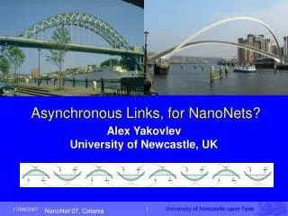
Asynchronous Links, for NanoNets? Alex YakovlevUniversity of Newcastle, UK
Feature size (nm) Relative 250 180 130 90 65 45 32 delay 100 Gate delay (fanout 4) Local interconnect (M1,2) Global interconnect with repeaters Global interconnect without repeaters 10 1 Source: ITRS, 2003 0.1 Motivation-1 • At very deep submicron, gate delay is much less than interconnect delay: total interconnect length can reach several meters; interconnect delay can be as much as 90% of total path delay in VDSM circuits • Timing issue is a problem, particularly for global wires • Multiple clock domains are reality, problem of interface between them • ITRS’05 predicted: 4x (8x) increase in global asynchronous signalling by 2012 (2020)
Motivation-2 • Variability and uncertainty • Geometry and process: for long channels intra-die variations are less correlated for different part of the interconnect, both for interconnects and repeaters • e.g., M4 and M5 resistance/um massively differ, leading to mistracking (C.Visuweswariah, SLIP’06) • e.g. 250nm clock skew has 25% variability due to interconnect variations (Y.Liu et.al. DAC’00) • Behavioural: crosstalk (sidewall capacitance can cause up to 7x variation in delay (R. Ho, M.Horowitz))
Synchronization required Multiple Clocks Arbitration required A Network on Chip Async Links
Example from the Past: Fault-Tolerant Self-Timed Ring (Varshavsky et al. 1986) For an onboard airborne computer-control system which tolerated up to two faults. Self-timed ring was a GALS system with self-checking and self-repair at the hardware level Individually clocked subsystems Self-timed adapters forming a ring
CommunicationChannel Adapter Much higher reliability than a bus and other forms of redundancy MCC was developed TTL-Schottky gate arrays, approx 2K gates. Data (DR,DS) is encoded using 3-of-6 Sperner code (16 data values for half-byte, plus 4 tokens for ring acquisition protocol) AR, AS – acknowledgements RR, RS – spare (for self-repair) lines
Outline • Token-based view of communication • Basics of asynchronous signalling • Self-timed data encoding • Pipelining • How to hide acknowledgements • Serial vs Parallel links • Arbiters and routers • Async2sync interface • CAD issues
Data exchange: token-based view • Question 1: when can Rx look at the incoming data? Data validity issue – Forming a well-defined token Data source tx rx dest
Data exchange: token-based view • Question 1: when can Rx looked at the data? Data validity issue – Forming a well-defined token • Question 2: when can Tx send new data? Acknowledgement issue – Separation b/w tokens Data source tx rx dest
Data source tx rx dest Data exchange: token-based view • Question 1: when can Rx looked at the data? Data validity issue – Forming a well-defined token • Question 2: when can Tx send new data? Acknowledgement issue – Separation b/w tokens These are fundamental issues of flow control at the physical and link levels The answers are determined by many design aspects: technology level, system architecture (application, pipelining), latency, throughput, power, design process etc.
Data source tx rx dest Tokens and spaces with global clocking • In globally clocked systems both Q1 and Q2 are resolved with the aid of clock pulses clk
Tokens and spaces Data • Without global clocking: Q1 can be resolved differently from Q2 • E.g.: Q1 – source-synchronous (mesochronous), bundled data or self-synchronising codes; Q2 – ack or stop signal, or by local timing source tx rx dest D_valid Clk_rx Clk_tx bundle
Tokens and spaces Data • Without global clocking: Q1 can be resolved differently from Q2 • E.g.: Q1 – source-synchronous (mesochronous), bundled data or self-synchronising codes; Q2 – ack or stop signal, or by local timing source tx rx dest D_valid ack ack bundle ack
Petri net model dest source Tx Rx Data Valid Tx delay Rx delay One way delay, but may be unsafe! dest source Tx Rx Data Valid ack Tx delay or ack Rx delay or ack Always safe but with a round trip delay!
Asynchronous handshake signalling Valid data tokens and safe spaces between them can be created by different means of signalling and encoding • Level-based -> Return-To-Zero (RTZ) or 4-phase protocol • Transition-based -> Non-Return-to-Zero (NRZ) or 2-phase protocol • Pulse-based, e.g. GasP • Phase-difference-based • Data encoding: bundled data (BD), Delay-insensitive (DI)
req req ack ack One cycle Handshake Signalling Protocols • Level Signalling (RTZ or 4-phase) • Transition Signalling (RTZ or 4-phase) req ack One cycle One cycle
req + ack One cycle Handshake Signalling Protocols • Pulse Signalling req req ack ack One cycle • Single-track Signalling (GasP) req ack
GasP signalling Pull up from pred (req) Pulse length control loops Pull up from here (req) Pull down here (ack) Pull down from succ (ack) Source: R. Ho et al, Async’04
Data encoding • Bundled data • Code is positional binary, token is determined by Req+ signal; Req+ arrives with a safe set-up delay from data • Delay-insensitive codes (tokens determined by the codeword values, require a spacer, or NULL, state if RTZ) • 1-of-2 (Dual-rail per bit) – systematic code, encoding, decoding straightforward • m-of-n (n>2) – not systematic, i.e. incur encoding and decoding costs, optimal when m=n/2 • One-hot ,1-of-n (n>2), completion detection is easy, not practical beyond n>4 • Systematic, such as Berger, incur complex completion detection
Data req ack One cycle Bundled Data RTZ: Data req ack NRZ: Data req ack One cycle One cycle
DI encoded data (Dual-Rail) RTZ: NULL (spacer) NULL Data.0 Data.1 Data.0 Logical 0 Logical 1 ack Data.1 ack One cycle One cycle NRZ: Data.0 Logical 0 Logical 1 Logical 1 Logical 1 Data.1 ack cycle cycle cycle cycle
DI encoded data (Dual-Rail) RTZ: NULL (spacer) NULL Data.0 Data.1 Data.0 Logical 0 Logical 1 ack Data.1 ack One cycle One cycle This coding leads to complex logic implementation; hard to track odd and even phases and logic values – hence see LEDR below NRZ: Data.0 Logical 0 Logical 1 Logical 1 Logical 1 Data.1 ack cycle cycle cycle cycle
DI codes (1-of-n and m-of-n) • 1-of-4: • 0001=> 00, 0010=>01, 0100=>10, 1000=>11 • 2-of-4: • 1100, 1010, 1001, 0110, 0101, 0011 – total 6 combinations (cf. 2-bit dual-rail – 4 comb.) • 3-of-6: • 111000, 110100, …, 000111 – total 20 combinations (can encode 4 bits + 4 control tokens) • 2-of-7: • 1100000, 1010000, …, 0000011 – total 21 combinations (4 bits + 5 control tokens)
DI codes completion detection and decoding • 1-of-4 completion detection is a 4-input OR gate (CD=d0+d1+d2+d3) • Decode 1-of-4 to dual rail is a set of four 2-input OR gates (q0.0=d0+d2; q0.1=d1+d3; q1.0=d0+d1; q1.1=d2+d3) • For m-of-n codes CD and decoding is non-trivial From J.Bainbridge et al, ASYNC’03
Incomplete DI codes Incomplete 2-of-7: Composed of 1-of-3 and 1-of-4 From J.Bainbridge et al ASYNC’03
t_1 before t_0 t_0 before t_1 ref t_1 t_0 sp0 sp0 sp1 sp0 sp1 data 0 0 1 0 Phase difference based encoding (C. D’Alessandro et al. ASYNC’06,’07) • The proposed system consists in encoding a bit of data in the phase relationship between two signals generated using a reference • This would ensure that any transient fault appearing on one of the reference signals will be ignored if it is not mirrored by a corresponding transition on the other line • Similarity with multi-wire communication
Phase encoding: multiple rail • No group of wires has the same delay • All wires toggle when an item of data is sent • Increased number of states available ( n wires = n! states) hence more bits/symbol • Table illustrates examples of phase encoding compared to the respective m-of-n counterpart
Phase encoding Repeater 1<3 3<1 2<3 3<2 1<2 2<1 Phase detectors (Mutexes)
Pipelines Dual-rail pipeline From J.Bainbridge & S. Furber IEEE Micro, 2002
The problem of Acking • Question 2 “when can Tx send new data?” has two aspects: • Safety (not to overflow the channel or when Tx and Rx have much variation in delay) • Performance (to maximize throughput and reduce latency) • Can we hide ack (round trip) delay?
To maintain throughput more pipeline stages are required but that costs too much latency and power First minimize latency along a long wire (not specific to asynchronous) and then maximize throughput (using “wagging tail buffer” approach) From R.Ho et al. ASYNC’04
Use of wagging buffer approach Alternate between top and bottom control From R.Ho et al. ASYNC’04
“Wagging tail buffer” approach reqtop Top and bot control channels work at ½ frequency of data channel acktop data reqbot ackbot
Why Serial Link? Less interconnect area Less routing congestion Less coupling Less power (depends on range) The relative improvement grows with technology scaling. The example on the right refers to: Single gate delay serial link Fully-shielded parallel link with 8gate delay clock cycle Equal bit-rate Word width N=8 Serial Link vs Parallel Link (from R. Dobkin) Link Length [mm] Serial Link dissipates less power Parallel Link dissipates less power Serial Link requires less area Parallel Link requires less area Technology Node [nm]
Serialization model Tx Rx … … Acking at the bit level
Serialization model Tx Rx Acking at the word level
Serialization model Tx Rx Acking at the word level (with more concurrency)
Serial Link – Top Structure (R.Dobkin, Async’07) • Transition signaling instead of sampling: two-phase NRZ Level Encoded Dual Rail (LEDR) asynchronous protocol, a.k.a. data-strobe (DS) • Acknowledge per word instead of per bit • Synchronizers used at the level of the ack signals • Wave-pipelining over channel • Differential encoding (DS-DE, IEEE1355-95) • Reported throughput: 67Gps for 65nm process (viz. one bit per 15ps – expected FO4 inverter delay), based on simulations
Uncoded (B) Phase bit (P) State bit (S) 0 0 0 0 1 0 1 1 0 0 Encoding –Two Phase NRZ LEDR • Two Phase Non-Return-to-Zero Level Encoded Dual Rail • “delta” encoding (one transition per bit)
Self Timed Networks • Router requires priority arbitration • Arbitration necessary at every router merge • Potential delay at every node on the path BUT • Asynchronous merge/arbitration time is average not worst case • Adapters to locally clocked cells require synchronization • Synchronization necessary when clocks are unknown • Occurs when receiving data (data valid), and when sending (acknowledge) BUT • Time can be long (2 cycles?) • Must assume worst case time (maybe)
Router priority • Virtual channels implement scheduling algorithm • Contention for link resolved by priority circuits Flow Control Link Merge Split
Asynchronous Arbiters • Multiway arbiters (e.g. for Xbar switches): • Cascaded mesh (latency ~ N) • Cascaded Tree (latency ~ logN) • Token-Ring (busy ring and lazy ring) (latency ~ from 1 to N) • Priority arbiters (e.g. for Routers with different QS): • Static priority (topological order) • Dynamic priority (request arrives with priority code) • Ordered (time-priority) - multiway arbiter, followed by a FIFO buffer
Lock MUTEX r1 s1 R1 s* q G1 C r MUTEX r2 s2 Priority Module R2 s* q G2 C r MUTEX r3 s3 R3 s* q G3 C r Lock Register s q C r* Static Priority Arbiter
Why Synchronizer? DATA 1 CLK DATA Q DFF 0 CLK Q 1 0 Metastability Metastability DATA Q Here one clock cycle is used for the metastability to resolve. DFF DFF CLK Two DFF Synchronizer
Bus Data Transceiver DSr LDS Device D LDTACK DSr LDS VME Bus Controller DSw LDTACK D DTACK DTACK Read Cycle Synthesis of Asynchronous link interfaces
DSr+ DSw+ DTACK- LDS+ D+ LDTACK+ LDS+ LDTACK- D+ LDTACK+ DTACK+ D- LDS- DSr- DTACK+ D- DSw-
DSr+ DSw+ D DTACK - DTACK LDS+ D+ synthesis LDTACK+ LDS+ LDS csc LDTACK - LDTACK+ D+ DSr DTACK+ D - LDS - LDTACK Logic asynchronous circuit DSr - DTACK+ D - DSw - csc + DSr+ DTACK- LDS+ LDTACK- LDTACK- LDTACK- DSr+ DTACK- LDS- LDS- LDS- LDTACK+ DSr+ DTACK- D+ D- csc - DSr- DTACK+ Complete State Coding (CSC) Boolean equations: LDS = D csc DTACK = D D = LDTACK csc = DSr