Download
1 / 65
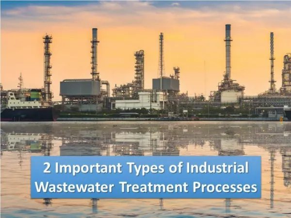
670 likes | 859 Vues
Physical Treatment Processes of Industrial Waste. Introduction of wastewater treatment methods and steps. Wastewater Bar Rack/ Comminutor Grit Chamber Equalization Basin Primary Settling Biological Treatment Secondary Settling Advance Wastewater Treatment.

E N D
Physical Treatment Processes of Industrial Waste
Introduction of wastewater treatment methods and steps Wastewater Bar Rack/ Comminutor Grit Chamber Equalization Basin Primary Settling Biological Treatment Secondary Settling Advance Wastewater Treatment Refer Table 5-1: Typical physical unit operations PRETREATMENT PROCESS PRIMARY PROCESS SECONDARY PROCESS TERTIARY PROCESS e.g: Depth Filter, Membrane filter, adsorption, Ion exchange, gas stripping etc
PRETREATMENT PROCESS -bar screen/ bar rack- Retain solid found in influent WW to the treatment plant Principle role light Coarse screen Remove coarse materials (e.g. sticks, rags, etc) from the flow stream that could : damage subsequent process equipment Screening Reduce overall treatment process reliability & effectiveness Contaminate waterway Fine screen (used in place of/following coarse screen) Where greater removals of solids are required to remove coarse materials (e.g. sticks, rags , etc) from the flow stream that could Protect process equipment Eliminate materials that may inhibit the beneficial reuse of biosolid
PRETREATMENT PROCESS -bar screen/ bar rack- May consists of parallel bars, rods or wires (coarse screen) perforated plate (fine screen) light The flow passes through the screen and the large solids are trapped on the bars for removal. Bar Screen/ Bar Rack The bar screen may be coarse (6 – 150 mm/ 0.25 – 6 inch openings) or fine (< 6 mm/0.25 inch openings). The bar screen may be manually cleaned or mechanically cleaned (performed frequently enough to prevent solids buildup and reduce flow into the plant)
PRETREATMENT PROCESS -bar screen/ bar rack-
PRETREATMENT PROCESS -bar screen/ bar rack-
PRETREATMENT PROCESS -GRIT chamber- • Remove grit (sand, egg shells or other heavy solid materials) that tends to settle in corners, bends, reducing flow capacity and ultimately clogging pipes and channels. light Grit chamber are provided to Protect moving mechanical equipment from abrasion Grit Chamber Reduce formation of heavy deposits in pipelines, channels & conduits Reduce the frequency of digester cleaning caused by exessive accumulation of grit Grit removal processes use gravity/velocity, aeration or centrifugal force to separate the solids from the wastewater. The most common method of grit disposal is transport to a landfill. In some large plants, grit is incinerated with solids
PRETREATMENT PROCESS -GRIT chamber- Once screened, the wastewater passes into two aerated grit chambers. Low-pressure air entering the grit chamber creates a rolling motion that causes grit and dense solids to settle to the tank bottom.
PRETREATMENT PROCESS -Comminutors & Macerators- - • used to intercept coarse solid & shred them in the screen channel The solids are cut up into a smaller, more uniform size of for return to the flow stream for subsequent removal. light The use of comminutor and macerator is adventageous in a pumping station to: Comminutors & Macerators Protect pump againts clogging by rags & large objects Eliminate the need to handle & dispose of screenings However, shredded solid (plastic bags, rags) tends to form ropelike strands & can clog pump impellers, sludge pipelines & heat exchangers). • Design consideration: • may be preceded by grit chambers to prolong life • Constructed with bypass arrangement
PRETREATMENT PROCESS -Comminutors & Macerators- - Macerators
PRETREATMENT PROCESS -FLOW EQUALIZATION- - • To minimize fluctuations in WW characteristics in order to provide optimum conditions for subsequence process • To provide adequate dampening of organic fluctuations in order to prevent shock loading to biological system • Provide adequate pH control • Provide cont. feed to biological system • Provide capacity for controlled discharge • To prevent high conc. of toxic materials from entering the biological treatment plants. Q Q t t Effluent for further treatment Bar Screen / communitor Grit Removal Equalization Basin Primary Treatment
PRETREATMENT PROCESS -FLOW EQUALIZATION- - • In-line arrangement: • all of the flow passes through the equalization basin • Can be used to achieve considerable amount of constituent conc. and flowrate damping. • Off-line arrangement: • Only flow above predetermined flow limit is diverted to equalization basin • Used to capture ‘first flush’ from combined collection system
PRIMARY PROCESS - ( primary & secondary process handle MOST of the NON-TOXIC wastewater) • Objectives: • Prepare WW for biological treatment (stabilize organic) • Remove + 60% SS and 35% BOD5 in sewage • Important because the reduction of the suspended solids and BOD5 • 1)lowers the O2 demand, • 2)decreases the rate of energy consumption and • 3)Reduces operational problem with downstream biological treatment • 4)remove scum (grease, oil, plastics, and other floatable materials) • and inert particulate matter which are not removed in grit chamber Principle form of primary treatment: SEDIMENTATION Note: sedimentation tank = sedimentation basin, clarifier, settling basin, settling tank
secondary PROCESS - • Objectives: • Speed up natural process of breaking down biodegradable organics • Remove up to 85 % SS and BOD5 • Devices/structures: • Activated sludge, extended aeration, rotating biological contacting (RBC), trickling filter, aerated lagoons, sequencing batch reactor etc • Biological degradation of soluble organics. • Mostly aerobically in an open aerated vessels @ lagoon • Speed up natural processes of breaking down biodegradable organics • Cannot remove N, P, heavy metals, pathogens, bacteria and viruses. • After treatment, microorganism and other carried over solids are allowed to settle. • A fraction of sludge is recycle • Excess sludge along with sediment solids has to be disposed off.
Tertiary/advanced PROCESS - • Objectives: • Nutrients removal, chlorination and dechlorination • Process added after biological treatment in order to remove specific group/ types of residual • Can remove + 95% BOD5, P, SS, bacteria and N • Devices/structures: • Filtration –removes SS • Granular Activated Carbon – removes organics • Chemical oxidation – removes oxidizable organics • Expensive to process LARGE VOLUME of WW
Selection of treatment process • Depends on the degree of treatment required to bring the quality of raw wastewater to a permissible level of treated wastewater • (eg. Effluent from the treatment plant) of organic matter or by substance added to the WW. Selection of treatment process • This ensures that the final effluent is either safe for disposal or acceptable for specific reuse or recycling. light Other significant factor that will influence the selection of a treatment system • Availability of funds and land at the treatment site • The topography of land at the treatment site • Non-availability of suitable mechanical equipment and skilled personnel for running and maintaining the plant. Ref: (Karia and Christian,2006)
Selection of treatment process The points to keep in mind while selecting the treatment process of organic matter or by substance added to the WW. • Reduction of inorganic material component of wastewater is much easier and cheaper than removal of organics contents of wastewater • Removal of suspended solids from wastewater requires lesser time and efforts than of colloidal and dissolved solids light • In many countries, the Environmental Protection Act requires at least the secondary treatment system for all publicly owned treatment works such as municipal wastewater treatment plant, so that effluent requirements of 30mg/L for BOD and 100mg/L of SS are achieved. Ref: (Karia and Christian,2006)
Basic design consideration Design criteria Strength & characteristics of WW Essential consideration Flow rate and their fluctuations Mass loading
Basic design consideration -strength & characteristics of ww- • The strength of wastewater is normally expressed in terms of pollution load, which is determined from the concentrations of significant physical, chemical and biological content of wastewater. of organic matter or by substance added to the WW. Strength & characteristics of WW • Characteristics of WW depend on the quality of water used by the community, culture of population, type of industries present & treatment given by industries to their WW. light The strength of WW measured as mass per unit volume of WW (Units: mg/L ) If characteristics of raw WW show the concentration of specific constituents like BOD & SS within the standard permissible limits, there is no need to treat the WW.
Basic design consideration • -FLOW RATE AND THEIR FLUCTUATIONS- • - • Is the quantity or volume of wastewater in terms of rates of organic matter or by substance added to the WW. • FLOW RATE & • THEIR • FLUCTUATIONS light • It is the total quantity of wastewater generated daily and to be treated every day. The volume of WW depend on the water consumption by the population for its various activities The flow rate units:m3/day or m3/s or MLD (million Litres per Day) Normally a treatment plant is designed on the daily average flow basis which is known as plant capacity. Example: 1 MLD (Million Litres per Day) plant means = the plant designed for 1 – ML daily average flow of WW
Basic design consideration • -mass loading- • - • The mass pollution load is defined as flow rate & strength of WW & is expressed as load per unit time of organic matter or by substance added to the WW. light • MASS LOADING • Example: • WW having 1000 m3/d flow & 200 mg/L (g/m3) BOD has the mass pollution load of BOD equal to 200 kg/d • (1000 m3/d X 200 g/m3 X 10-3 g/kg) In the case of treatment plant that receives flow of combined sewerage system, the seasonal variation in the rainy season will lower down the BOD & SS concentration due to the dilution because of the added amount of storm water. On the other hand, a higher concentration of BOD & SS may be observed during the dry weather period. Therefore, in almost all cases, a flow-weighted average should be used because it is more accurate method of analysis
Basic design consideration • -mass loading- • - Flow-weighted average Where , XW = flow –weighted average concentration on the constituent Xi = average concentration of the constituent during the “i” time period Qi = average flow rate during “i” time period
Basic design consideration • -design criteria- • - of organic matter or by substance added to the WW. • The data determined through the research and laboratory scale model studies as well as those obtained from the operational experience of field and pilot scale WW treatment facility. The values of such guideline parameters are called design criteria and available in the literature. • The most frequently assumed criteria for designing a conventional WW treatment plant (WWTP): • Detention period or time • Flow through velocity • Settling velocity • Surface loading rate @ over flow rate • Weir loading rate • Organic loading (BOD @ COD @ VSS loading) • Food to Microorganism ratio, F/M • Mean cell Residence Time • Hydraulic Loading • Volumetric Loading • Basin geometry (L:B:D) length, breadth and depth ratio.
ASSIGNMENT 1 • Explain process that involves in • Activated sludge • Extended aeration • Rotating biological contacting (RBC) • Trickling filter • Aerated lagoons • Sequencing batch reactor (SBR) • Granular activated carbon Please submit - 9/10/2014 (during class).
Sedimentation process Process of heavier solid particles in suspension, settle to the body of tank by gravity Removal of SS from WW light Depends on Velocity of flow Size and shape of particles Sedimentation Viscosity of water Types of particles Discrete /non-flocculant particles Size & velocity constant during the settling Flocculant particles Size & velocity fluctuates during the settling Common operation & found almost in WWT plant LESS COSTLY than many other treatment processes
Particles settling theory The settling of discrete particles can be analysed by means of the classic laws of sedimentation by Newton & Stokes. Gravitational force, Frictional drag force, Refer page 363 in text book
Design of sedimentation PROCESS In the design of sedimentation basin, the settling velocities of the particles MUST be KNOWN. light The knowledge of settling velocity of particle is used to determining the depth of a treatment unit to separate the suspended solids (particulate matter) by gravity settling and for checking the adequacy of length or diameter of a tank to remove particles before the effluent flows out of the basin. sedimentation Where, vc = particle settling velocity Q = flowrate of WW A = surface of sedimentation tank
sedimentation PROCESS Settling zone Inlet zone Settling zone Inlet zone Outlet zone Outlet zone Outlet zone Inlet zone Sludge zone Sludge zone UPFLOW BASIN CIRCULAR BASIN RECTANGULAR BASIN Outlet zone Inlet zone Settling zone Idealized discrete particles settling in 3 different type of basins
Types of basin Circular Basin Rectangular Basin
Classification of particles settling Classification of particles settling Type 1 Discrete Type 3 Zone Type 2 Flocculant
Type 1 : discrete Particles DOES NOT change in size, shape & density during the settling process Particles settle discretely at a constant velocity Settle as individual particles & do not flocculate Occurs during: Presedimentation for sand removal Grit Chamber
Type 2 : flocculant Flocculate during sedimentation Particles size constantly changing Settling velocity is changing increase with depth & extent of flocculation Occurs during: Alum or iron coagulation Primary sedimentation basins
Type 3: zone water Solid settle The floc particles adhere together & the mass settle as a blanket (layer) Distinct clear zone & sludge zone present Concentration HIGH (greater than 500 mg/L) Occurs during: Activated sludge sedimentation Sludge thickeners
Type 3: zone High of sludge liq interface B B Transition zone B A A A Transition Zone Compression Zone C Settling Zone C D Dense solid D D Settling properties of flocculated sludge Initially, all the sludge is at uniform concentration A A settling proceeds, the collapsed solid on the bottom of the settling unit (D) build up at constant rate. C is zone of transition through which the settling velocity decreases Through the transition zone C, the settling velocity will decrease due to the increasing density & viscosity of the suspension surrounding the particles. When the rising layer of settle solid reaches the interface, a compression zone occur.
Design criteria The following design criteria are generally assumed to design a Primary Settling Tank / Sedimentation A) GENERAL Refer Table 5-20 in textbook
Design criteria B) DIMENSIONS C) TECHNICAL
SEDIMENTATION /clarification PROCESS Primarily used in WWT to separate solids from liquids in effluent streams. light Types Clarifiers Criteria for sizing clarifier (settling tank) Tank depth at the side wall Overflow rate (surface loading rate) Detention time Scour velocity
Criteria for sizing clarifier (settling tank) -overflow rate (surface settling rate)- Definition: The average daily flow rate divided by the surface area of the tank. Clarifiers Average daily flowrate (m3/day) overflow rate @ surface settling rate (m3/m2d) Total surface area of the tank (m2)
Criteria for sizing clarifier (settling tank) -depth of tank- The water depth at the side wall measuring from the tank bottom to the top of the overflow weir. Depth of tank Effluent weir Exclude the additional depth resulting from slightly sloping bottom that is provided in both circular and rectangular clarifiers. Influent Influent H Occupied with sludge Effluent weir loading (typical= 250 m3/m.d) is equal to quantity of WW flowing divided by the total weir length, Lw Average daily flowrate (m3/day) Total weir length (m)
Criteria for sizing clarifier (settling tank) -detention time- length of time a particle or a unit volume of WW remains in a reactor Detention time Tank volume (m3) Detention time = (day) Average daily flowrate (m3/day)
Criteria for sizing clarifier (settling tank) -Scour velocity horizontal velocity through the tank to avoid resuspension of settled particles Scour Velocity Where: VH = horizontal velocity that will just produce scour (m/s) k = cohesion constant that depends on type of material being scoured (unitless) s=specific gravity of particles g=acceleration due to gravity (9.81 m/s2) d=diameter of particles f=Darcy-Weisbach friction factor (unitless)
flotation • Used for the removal of lighter SS, oil & grease. of organic matter or by substance added to the WW. light • Also used to concentrate biological sludge and to separate both the fine solid and a liquid particles from the liquid phase Flotation Introducing fine gas (air) bubbles into the liquid phase. Bubbles will attach to the particulate matter , thus increase the buoyant force, cause the particle to rise to the WW surface . Floated particles are collected by skimming operation . Thus, the operation is just the opposite of that of gravity sedimentation where particles get removed at the bottom of the tank. Degree of particle removal can be enhanced by addition of chemical additives Advantage: Removal of smaller particles in a shorter time and more complete.
flotation Frequently used in industrial WW treatment Frequently used in Municipal WW treatment
flotation WW is first saturated with air either directly in the aeration tank or by introducing air at the pump side (at Patm) Then partial vacuum is applied. This results in generation of small air bubbles which attached themselves to the particles and make them rise, forming a scum blanket. Typically a cylindrical tank maintain under vacuum is applied and continuously fed with WW air bubbles are formed by introducing the air in the form of gas phase directly into the liquid phase either by a revolving impeller or through air diffusers at the atm pressure. Flotation is achieved first by dissolving the air in the WW or in a portion of treated effluent (liquid) under high pressure in the pressurizing or retention tank and then reducing the pressure of the WW through a pressure-reducing valve to atmospheric level during feeding it to the flotation tank to form the rising air bubbles.
flotation Systems based on recirculation of effluent In large treatment plants, normally 15-20% of the effluent is recycled Small treatment plants operate without recycling the effluent. Example: Dissolved-air Flotation (DAF) Effluent is recirculated Effluent is not recycled A predetermine fraction of effluent from the flotation unit is taken to the pressurized tank where it is pressurized, and the air is dissolved below the saturation level. The flow is then mixed with the influent entering the flotation unit through a pressure-reducing valve so that air bubbles come out from the recycled flow and get attached with the particles of incoming raw wastewater that are to be removed by flotation. Wastewater influent is first retained for some time in the pressure tank where pressure of wastewater is increased to as high as 275-350kPa and air is dissolved in it. Then the flow is fed to the flotation unit through a pipeline having a pressure-reducing valve. As the pressure is released from wastewater, the dissolved air comes out of the solution as fine bubbles which are used for particle separation by flotation.
Dissolved-Air Flotation (no recycle) Please refer diagram in your textbook
Dissolved-Air Flotation (with recycle) Please refer diagram in your textbook pg 420