Download
1 / 67
680 likes | 924 Vues
Efficiency of Combustion Plant. 朱信 Hsin Chu Professor Dept. of Environmental Engineering National Cheng Kung University. 1. Plant Efficiency. From last chapter, the general energy balance of a combustion system was CV + H R = H P + Q c + Q u (1)

E N D
Efficiency of Combustion Plant 朱信 Hsin Chu Professor Dept. of Environmental Engineering National Cheng Kung University
1. Plant Efficiency • From last chapter, the general energy balance of a combustion system was CV + HR = HP + Qc + Qu (1) • This expression can be used to explore the meaning of efficiency of the system.
Intuitively, the efficiency of a device such as a boiler would be interpreted as the rate at which useful heat is extracted from the device divided by the rate at which heat, in the form of the calorific value of the fuel being consumed, is supplied to the boiler.
In the specific case of a boiler supplying hot water, the instantaneous efficiency is given by the rate of gain of enthalpy of the working fluid divided by the equivalent thermal energy input rate from the fuel: • If the net calorific value of the fuel is used we should refer to the “net efficiency” of the boiler, if the gross calorific value is used then the figure obtained is called the “gross efficiency”. • The net efficiency will have a higher numerical value than the gross efficiency.
Some boilers are designed to cool the flue gases to below their dew point (typically just below 60℃). • These condensing boiler are thus capable of higher efficiencies as they are able to recover some of the latent heat present in the water vapor in the flue gas.
If the flue gas is cooled significantly below the dew point of the water vapor present, then an efficiency figure greater than 100% can be obtained if the efficiency is based on the net calorific value. • For this reason, the efficiency of condensing devices should always be based on the gross calorific value of the fuel.
Before developing the efficiency of combustion appliances, it is worth taking a closer look at some of the terms in the steady-state energy balance of equation (1). • (a) Enthalpy of the reactants (HR) If the temperature of the air and fuel entering is close to the datum value, 25℃, then clearly HR will not be a significant term in the balance. • In other circumstances, such as when the fuel and air are preheated, then it will make a significant contribution to the equation.
It will be seen later, when describing practical measurements of combustion efficiency, that when the temperature of the entering fuel/air is other than 25℃, this can be partly compensated by basing the enthalpy in the combustion products with reference to the temperature of the fuel and air entering. • This is acceptable provided that the thermal capacity rates (mass flow rate × specific heat of the mixture) of the fuel/air mixture entering the system and the combustion products leaving the system are approximately equal.
For most practical purposes, the combustion air is treated as a mixture of dry gases. • The enthalpy of the combustion air above or below the reference temperature of 25℃ is therefore given simply by the thermal capacities (mass × specific heat) of each of the components of the mixture multiplied by the difference in temperature between the mixture and 25℃.
When developing a treatment of thermal efficiency in the condensing regime, the presence of water vapor in the air entering is taken into account, and a latent heat is incorporated into the value of HR in this section.
(b) Thermal losses from the plant (Qc)In simplified thermodynamic analyses the term is often neglected, as the heat transfer from the outer surfaces of a boiler is small compared to the throughput of the device. • Clearly this term will be of decreasing significance as the size of the boiler increases, but a rough estimate of the figure is about 3-5% of the output of the boiler.
If any unburned fuel is present in the flue gas, this will be an energy loss from the system. • An important objective of burner design is to obtain complete combustion of the fuel, hence good design and operation should keep this term to negligible proportions.
We can regard a combustion appliance as a two-component system. • The first-component, the burner, has the task of converting the chemical energy in the fuel into thermal energy in the flame as efficiently as possible.
To bring this about, there should be no unburned fuel in the flue gas and the fuel should be burned at an air-to-fuel ratio as close to the stoichiometric value as possible. • Excess air merely passes through the system as a passenger and is warmed in the process, which inevitably leads to a reduction in the efficiency of the system.
In a buoyancy-driven system such as a domestic gas-fired boiler, the energy for mixing the fuel and air streams is low, hence large quantities of excess air are used to avoid unburned fuel leaving the boiler. • In this instance, the unburned fuel will be in the form of carbon monoxide, so there are significant safety implications as well.
The second component of the system is a heat exchanger which transfers heat from the combustion products into a working fluid. • The heat exchanger will thus have a gas on the combustion side of the exchanger and possibly a gas, liquid or boiling liquid on the other side of the exchanger.
At first sight it would seem that the heat exchanger should be as large (effective) as possible in order to extract maximum heat from the system. • In fact, there are a number of constraints on the size of the exchanger that limit this.
The effectiveness of a heat exchanger is primarily dependent on its overall coefficient of heat transfer and its heat transfer area (i.e. its size). • The greater the surface area of the heat exchanger the higher will be its capital cost, and also the power required to push the combustion gases through it will increase.
Increasing the heat transfer coefficient (by, for example, the use of turbulence promoters) will also increase the energy needed to maintain the flow through the device. • The last constraints that will be touched on here are concerned with the low gas temperatures which must accompany high heat recovery in the heat exchanger.
The temperature of the heat-extracting fluid on entering must always be lower than the temperature of the flue gas on leaving. • The implication of this is that very high boiler efficiencies can only be realized where there is a demand for low-grade heat. • There are comparatively few applications where this is the case, although the heating of buildings is an important exception to this.
Finally, it is important to avoid the possibility of corrosion arising from unplanned condensation occurring within the combustion device, the heat exchanger or the flue. • This consideration is particularly important with sulfur-bearing fuels, as any such condensate is acidic and therefore highly corrosive.
2. Direct Determination of Efficiency • The basic measurements required are the mass flow rate, together with the temperatures of the heat-extracting fluid on entering (return) and leaving (flow), and the flow rate of the fuel supplied. • The value of efficiency obtained from such tests will depend on three factors: the fluid mass flow rate, the return temperature and the load on the device, which will determine its firing rate.
Clearly the low return temperature together with a high flow rate will provide a low mean fluid temperature on the cool side of the heat exchanger, thus maximizing the heat transfer rate. • Most small boilers have a simple on/off control mode in which the burner is either firing at its fuel rate or is turned off. • The hysteresis inherent in this control gives a variation of the temperature of the water in the boiler about the set point (Fig. 6.1, next slide).
The variation of efficiency with load is shown in Fig. 6.2 (next slide) for a typical natural draught domestic boiler (on/off control) and a larger unit of commercial size (continuous modulation of air and fuel). • It can be seen that the efficiency falls off markedly at low loads.
3. Inferential Measurement of Efficiency • Inferential measurement is based on readings which enable the enthalpy losses in the flue gas (per unit mass of fuel) to be related to the calorific value of that fuel. • Rearranging eq. (1), and assuming that Qc is negligible, we get:CV = (HP - HR) + Qu • The term in brackets represents the difference between the enthalpy of the air/fuel and that of the combustion products, measured from the reference temperature of 25℃.
Given that the efficiency of the system is defined by Qu/CV, we can write: • Knowing the calorific value of the fuel, the values of HP and HR now need to be determined. • In order to evaluate these, it is necessary to know the temperature and composition of the flue gas and of the fuel/air mixture entering.
If the following conditions apply:The chemical composition of the fuel is known.Combustion of the fuel is complete.There is negligible carbon monoxide in the products. • A measurement of any one of the species present in the combustion products will enable the air-to-fuel ratio on entering to be calculated, together with the composition of the combustion products.
Once the composition of the flue gas is known, the mass of each constituent is easily obtained and hence the enthalpy of the flue gas above the required datum. • The combustion products from a hydrocarbon fuel will contain a certain mass of water vapor. • If the latent heat term for this water vapor is included in the enthalpy of the flue gas then the gross calorific value for the fuel must be used in the calculation, and the result will be the gross efficiency of the device.
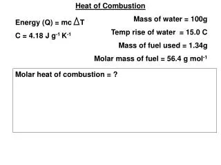
Example 1:A propane-fired boiler is operating in a plant room where the ambient temperature is 15℃.Measurements at the exit from the heat exchanger showed a flue gas temperature of 240℃ and a reading of 9% O2. • Estimate the gross and net efficiencies of the boiler. Take the net calorific value of propane as 46.48 MJ/kg.
Solution:In this calculation it will be necessary to work in both volumetric and mass units. • The stoichiometric equation is an appropriate starting point:C3H8 + 5O2 + 18.81N2 → 3CO2 + 4H2O + 18.81 N21kg 3.636 11.97 3 1.636 11.97 • The combustion products contain 3 vols CO218.81 vols N2x vols excess air, consisting of 0.21x vols O2 and 0.79x vols N2
So if there is 9% oxygen in the products giving x=16.36 vols air • The stoichiometric air requirement is so the excess air is
The quantities of reactants and products can now be established on a mass basis:Reactants: 1 kg C3H8 3.636 kg stoichiometric oxygen 2.50 kg excess oxygen 20.19 kg nitrogenProducts: 3 kg CO2 1.636 kg H2O 2.5 kg O2 20.19 kg N2
To establish the enthalpies of the reactants and products Reactants (mean temperature 25℃)specific heats: C3H8 1.97 kJ/kg/K O2 0.91 N2 1.04HR = (15-25){(1×1.97)+(6.1×0.91)+(20.19×1.04)} = -302.5 kJ/kg of fuel
Products (mean temperature 133℃):Specific heats: CO2 0.94 kJ/kg/K H2O 1.91 O2 0.95 N2 1.05HP = (240-25){(3.0×0.94)+(1.636×1.91)+(2.5×0.95)+(20.19×1.05)}= 6,346.6 kJ/kg of fuel • HP-HR = 6,346.6 + 302.5 = 6,649 kJ/kg of fuel
The mean temperature over the interval (240-15)is 113℃ and the specific heats at this temperature are: CO2 0.92 kJ/kg/K H2O 1.90 O2 0.94 N2 1.04 • Hence:HP–HR =(240-15){(3.0×0.92)+(1.036×1.90)+(2.5×0.94)+(20.19×1.04)} =6,574 kJ/kg of fuel
The error resulting from this assumption, which is due to the thermal capacities (mass × specific heat) of the constituents of the flue gas being different from those of the reacting air and fuel, amounts to around 1% in this case. • The net efficiency of the boiler can now be calculated from:
To get the gross efficiency we must add a latent heat term equal to the mass of water vapor produced (1.636 kg per kg fuel) multiplied by the latent heat of evaporation of water at 25℃ (2,422 kJ/kg), i.e. 3,995 kJ. • The term (HP-HR) now becomes (6,649+3,995 )=10,644 kJ, and the gross calorific value of the fuel is (46,480+3,995)=50,475 kJ/kg. • The gross efficiency of the boiler is thus:
4. Efficiency and Flue Gas Temperature • The temperature of the flue gas as it leaves the combustion device clearly determines its thermal efficiency; neglecting case losses, the lower the temperature of the combustion products on leaving, the greater will be the thermal efficiency of the system. • Next slide (Fig. 6.3)The relationship between gross efficiency and flue gas temperature for the combustion of a propane-fired heating device operating with 25% excess air.The air/fuel temperature on entering: 25℃.
5. Flue Gas Dew Point • One of the simplest ways of finding the dew point temperature of the flue gases is based on the volumetric percentage of water vapor in the combustion products. • As a consequence of the ideal gas laws, if x% of the molecules in a gas mixture are of a given species (e.g. water vapor), then they will exert x% of the total pressure of the mixture.
For example, if the wet flue gas composition shows 10% water vapor and the flue gas is at atmospheric pressure, then the partial pressure of the water vapor is 0.1 atm. • The water vapor will start to condense when the temperature falls to such a level that its partial pressure is equal to the saturation vapor pressure at that temperature.
The relationship between saturation vapor pressure and temperature is generally obtained from steam tables. • Alternatively, the saturation vapor pressure (in kPa) can be calculated from:log10Ps = 30.59051 - 6.2log10T + 2.4804 × 10⁻³T - (3142.31/T) (2)Where T is the temperature in degrees Kevin.
When considering the condensation of water vapor from the products of combustion, it is appropriate (and most accurate) to take into account the moisture present in the combustion air. • We usually quantify the moisture present in the atmosphere in terms of the relative humidity of the air.
Relative humidity is a property which affects our sensation of comfort. • If the relative humidity is less than 30% the environment will seem excessively dry, if the relative humidity rises to over 70% it will feel “close” or stuffy.
Mositure content is frequently given the symbol g and is defined as the mass of water vapor (in kg) associated with 1 kg of dry air. • The moisture content at saturation can be calculated, with adequate accuracy for this task, from:
If the gas mixture is at standard atmospheric pressure (1.01325 bar) this expression becomes: (3) • For example, at 15℃ the saturation vapor pressure of air is 0.01704 bar. Substitution of this value into eq. (3) gives a saturation moisture content of 0.017 kg H2O/kg dry air.
A typical value for the relative humidity of the ambient air is 60%. • Air at 60% relative humidity at a temperature of 15℃ will have a moisture content of about 0.01 kg/kg.
Example 2:Estimate the dew point of the flue gas from the combustion of propane with 25% excess air, as in the example 1: boiler efficiency calculation. • Solution:From calculation in Example 1, the stoichiometric combustion of 1 kg of propane requires 15.6 kg air (taken to be dry).At a moisture content of 0.01 kg/kg dry air, this quantity of air will contain 0.156 kg water vapor.