Download
1 / 22
230 likes | 1.14k Vues
EQUIVALENT CIRCUIT MODEL FOR THE CELL MEMBRANE. Reported by: Valerie Chico ECE 5. Nerve Membrane. The nerve membrane is a lipid bilayer that is pierced by a variety of different types of ion channels Types of Ion Channels Passive (always open) Active (gates that can be opened).

E N D
EQUIVALENT CIRCUIT MODEL FOR THE CELL MEMBRANE Reported by: Valerie Chico ECE 5
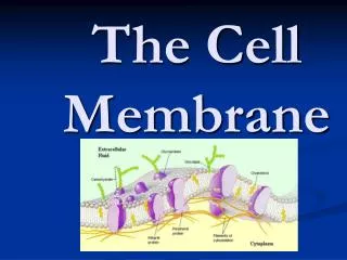
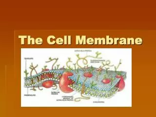
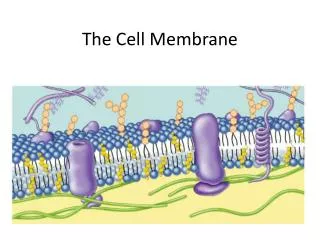
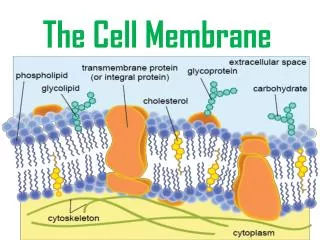
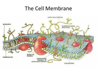
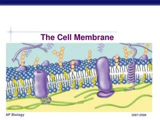
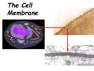
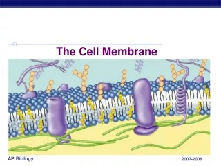
Nerve Membrane • The nerve membrane is a lipid bilayer that is pierced by a variety of different types of ion channels Types of Ion Channels • Passive (always open) • Active (gates that can be opened). Note : Each ion channel is also characterized by its selectivity.
Three types of Passive Electrical Characteristics • Electromotive Force • Resistive • Capacitive Remember: Active Na-K pump maintains Vm across the cell membrane
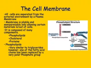
Electromotive Force Properties The three major ions Kþ, Naþ, and Clare differentially distributed across the cell membrane at rest and across the membrane through passive ion channels.
This separation of charge exists across the membrane and results in a voltage potential Vm as described by the Goldman Equation
Across each ion-specific channel, a concentration gradient exists for each ion that creates an electromotive force, a force that drives that ion through the channel at a constant rate. The Nernst potential for that ion is the electrical potential difference across the channel and is easily modeled as a battery, as is illustrated in Figure 11.11 for Kþ. The same model is applied for Naþ and Clwith values equal to the Nernst potentials for each.
Resistive Properties It resists the movement of electrical charge through the channel. This is mainly due to collisions with the channel wall where energy is given up as heat. The term conductance, G, measured in Siemens (S), which is the ease with which the ions move through the membrane, is typically used to represent resistance. Since the conductances (channels) are in parallel, the total conductance is the total number of channels, N, times the conductance for each channel, G’ G =N xG ’ 1
Conductance is related to membrane permeability, but they are not interchangeable in a physiological sense. Conductance depends on the state of membrane, varies with ion concentration, and is proportional to the flow ions through a membrane. Permeability describes the state of the membrane particular ion. Consider the case in which there are no ions on either side the membrane. No matter how many channels are open, G ¼ 0 because there ions available to flow across the cell membrane (due to a potential difference). the same time, ion permeability is constant and is determined by the state of membrane.
Capacitive Property Capacitance occurs whenever electrical conductors are separated by an insulating material. In the neuron, the cytoplasm and extracellular fluid are the electrical conductors and the lipid bilayer of the membrane is the insulating material (Fig. 11.3). Capacitance for a neuron membrane is approximately 1 mF=cm2. Membrane capacitance implies that ions do not move through the membrane except through ion channels. The membrane can be modeled using the circuit in Figure 11.15 by incorporating membrane capacitance with the electromotive and resistive properties. A consequence of membrane capacitance is that changes in membrane voltage are not immediate but follow an exponential time course due to first-order time constant effects. To appreciate the effect of capacitance, the circuit in Figure 11.15 is reduced to Figure 11.16 by using a The´venin equivalent for the batteries and the resistors with RTh and VTh given in Equations 11.35 and 11.36.
The time constant for the membrane circuit model is t ¼ RTh Cm, and at 5t response is within 1% of steady state. The range for t is from 1 to 20ms in a typical neuron. In addition, at steady state, the capacitor acts as an open circuit and VTh ¼ Vm, as it should.
Change in Membrane Potential with Distance The larger the diameter of the dendrite, the smaller the resistance to the spread of current from one section to the next
resistance is important. Most of the current flows out through the section into which the current was injected since it has the smallest resistance (RTh) in relation to the other sections. The next largest current flowing out of the membrane occurs in the next section since it has the next smallest resistance, RTh þ Ra. The change in Vm, DVm, from the injection site is independent of Cm and depends solely on the relative values of RTh and Ra. The resistance seen in n sections from the injection site is RTh þ n Ra. Since current decreases with distance from the injection site, then DVm also decreases with distance from the injection site because it equals the current through that section times RTh. The change in membrane potential, DVm, decreases exponentially with distance and is given by