Documenting Software Architectures
Learn about software architecture, its importance, structures, views, and documenting methods. Explore examples, concepts, models, and current practices in the field.

Documenting Software Architectures
E N D
Presentation Transcript
Documenting Software Architectures These notes are my personal view of the concepts presented on Duran-Limon’s paper: Documenting Software Architectures: The practitioner Community Perspective. Dr. Rogelio Davila
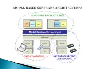
Software Architectures • Software architecture is a discipline looking to reach higher abstraction levels for architecture design. • This approach alleviates the software development complexity and makes this process less error-prone.
Software Architectures “The software architecture of a program or computing system is the structure or structures of the system, which comprise software elements, the externally visible properties of those elements, and the relationships among them.” [Bass,03]
Software Architectures Important concepts • A software architecture comprises multiples structures. • Each structure represents a different view of the system. • Each structure concentrates in one aspect of the system.
Software Architectures Examples (1) The Architecture of a building has many structures: • Building structure • Electricity supply structure • Water supply structure and so on
Software Architectures • A structure is a set of elements with an organizational pattern.
Software Architectures • A view or view type denotes a representation of a structure. • A view type instance is a particular representation for a particular structure of a given system.
Software Architectures • A view may have several representations of the same structure. E.g. A database structure can be expressed using an Entity-relationship model or a SQL script (both representations are equivalent as they express the same elements and relationships.
Software Architectures Architecture View 1 1 1 * * 1 Representation Structure
Software Architectures Views can be organized in three different categories: • Module: module views represent structures including units of functionality as elements. E.g. module decomposition and the class inheritance view. • Component-and-connector: structures containing runtime elements such as processes and threads .E.g. concurrency and communication processes views. • Allocation: structures involving assignment relations. E.g. In a Deployment structure, software elements are assigned to hardware elements.
Software Architectures These categories can be further classified into: • Non-runtime views: module and some Allocation views. E.g. an implementation structure where implementation files are mapped to a file structure. • Runtime views: component-and-connector and some Allocation views. E.g. a deployment view, involving mobile code (e.g. mobile agents).
Software Architectures This area is roughly divided between two groups: • The researcher community • The Industry practitioner community
Software Architectures One of the main differences between these two communities involves the approach taken to describe software architectures.
Documenting Software Architectures Researcher community • advocates using architecture description languages (ADLs) which represent formal notations for describing architectures in terms of coarse-grained components and connectors. • ADLs are usually domain specific languages.
Documenting Software Architectures Industry practitioners community • Advocate using a general purpose language, UML. • UML has become a standard de facto for documenting software systems.
Documenting Software Architectures Current tendency • UML has become a standard de facto for documenting software systems. • ADLs provide solid support for formal verification and correction but it is considerably more difficult to use than UML. • Tendency to merge: UML 2.0 includes some extensions from the ADL world
Documenting Software Architectures However, current practice for documenting software architectures is commonly informal and in many cases based in box-and-arrow notations.
Documenting Software Architectures Major disadvantages • Ambiguity in the descriptions. • Lack of support for detecting inconsistencies. • Inability to establish traceability between design and code. • Architectural details incompleteness (most of the times reverse engineering is needed to detect them).
Documenting Software Architectures Observations • There exist notations for architectural descriptions. • They are applied in an ad hoc way. • Need for more solid methodologies for documenting in a structured and coherent manner.
Approaches to SA Documentation Current Models • Kruchten’s 4+1 view model • Soni’s view (SA as used in industrial applications). • Rational Unified Process (RUP). Derived from Kruchten’s approach. • IEEE 1471 standard. A recommendation for SA documentation. • Bass’s approach. Kruchten’s and Soni’s approaches are foundational and have influence on the others.
Kruchten’s Approach The 4+1 view model From Kruchten’s perspective a software architecture can be described by using for view categories: • Logical view • Process view • Physical view • Development view Use cases scenarios constitute the fifth view.
Kruchten’s Approach Logical View Represents functionality elements and it is a module view category. Encompasses different view types such as the class and entity-relationship views. Static structures are represented by object and class diagrams. Dynamic behavior is represented by interaction, state, activity and deployment diagrams.
Kruchten’s Approach Process View Involves runtime elements, hence, it is a component-and-connector view category, includes concurrency, synchronization and distribution aspects of a system's design. Views are represented by interaction, state, activity and deployment diagrams.
Kruchten’s Approach Physical view It is an allocation view category, that involves the mapping of software elements to hardware units. Represented by deployment diagrams.
Kruchten’s Approach Development view Shows how implementation elements are allocated to the development environment. It is an allocation view category which is represented by component diagrams and packages. It includes, for example, an implementation view and a work assignment view.
Approaches to SA Documentation Use cases (or scenarios) view The main role of scenarios is twofold. • It is a driver which conducts design by discovering missing architectural elements. • It is a tool to validate and illustrate the architecture design.
Soni’s Approach This approach is based on a survey carried out on number of industrial applications whereby the sistems’ software architectures where analysed. They found the structures involved in the systems reviewed fall into four categories.
Soni’s Approach Soni’s Categories • Conceptual architecture. Represents an architecture in terms of components and connectors. This category is the highest level one. • Module architecture. Involves functional decomposition and layered structures. • Execution architecture. Includes runtime elements such as processes and communicating protocols. • Code architecture. Maps code files to the file system structure. It is used basically for building and installing the system.
Soni’s Approach In Soni’s approach relationships among views are identified. • Mirroring relationship. It is the case when an element in one view appears in others. • Hybrid views. It involves two or more views in a single view. • Correspondence relationship. It involves explicitly describing associations among elements of different views.
RUP Approach • It is based on Kruchten’s 4+1 model. • A view is considered a projection of a system on one of its relevant aspects. • A projection emphasizes certain aspects and ignores others. • UML diagrams are used to represent views.
RUP Approach • It is based on Kruchten’s 4+1 model. • A view is considered a projection of a system on one of its relevant aspects. • A projection emphasizes certain aspects and ignores others. • UML diagrams are used to represent views. • It includes the logical, process, deployment, physical and scenarios views from Kruchten’s model.
IEEE 1471 standard • Elements defined in this recommendation are viewpoints, views and architectural models. • Viewpoints are similar to view categories. • A view is the “actual” representation of a particular system. Hence, views are view type instances. • Architectural models are diagrams. A view may involve one or more diagrams. • The use of multiple views for describing an architecture is fundamental in the recommendation.
IEEE 1471 standard Architectural documentation format • Overview information • Identification of stakeholders and concerns • Selection of viewpoints • One or more views • Consistency among views • Architectural rationale
IEEE 1471 standard • Overview information A summary of the whole system. It includes details such as what the system is about. • Identification of stakeholders and concerns Identify the stakeholders involved together with their concerns. The minimum set of stakeholders includes: user, acquirers, developers and maintainers.
IEEE 1471 standard • Selection of viewpoints Each viewpoint should include involved stakeholders, concerns, notations and associated modeling methods. • One or more views Each view must include introductory information, diagrams associated with modeling methods and configuration information.
IEEE 1471 standard • Consistency among view It requires an analysis of consistency across views. • Architectural rationale It includes an explanation of the rationale behind the selected architectural designs.
Bass’ Approach • This model defines the three view categories: module, component-and-connector and allocation. • No particular view or set of views are advocated. • Views are selected based on both the quality attributes (also called non-functional requirements) and the stakeholders involved. • Use quality attributes to obtain the architectural patterns in charge of guiding the design. • For the involved Stakeholders, the relevant views are selected.
Bass’ Approach • The documentation consists in two parts: First, a general overview which defines: • How the document is organized • What is the system about • A diagram showing the mapping between views • The rationale behind the system’s design among other things
Bass’ Approach Second, the selected views in the following format: • Primary presentation of the view. A brief explanation together with a graphical representation (if possible). • Element Catalogue. Explains each element in the view and their relations. • Context Diagram. It shows the relations of the view’s elements with external elements. • Variability Guide. It documents variation points such as specifying the valid options that can be selected.
Bass’ Approach • Architecture Background. Explains the rationale behind the structure depicted in the view. • Glossary of terms. It is a brief description of terms used in the view. Bass advocates an iterative approach named attribute-driven design(ADD).
View-driven Documentation • Assumes there is a minimal set of views. • The whole set of views can be obtained based on quality attributes and the stakeholders involved. • There is a minimal set of views that should be included in most systems’ designs. This is based in the fact that there is a minimal set of stakeholders involved in most systems.
View-driven Documentation • Associated with that set of stakeholders there is a minimal set of views. • Minimal set of stakeholders: Project Manager, System Architect, Developers, Testers and integrators, maintainer, Customer and End User.
View-driven Documentation Minimal set of views • Client Server • Decomposition • Deployment • Layered • Class/Procedures • Uses • Implementation
View-driven Documentation • The VDD method is based on an iterative refinement process of views. • The views are selected based on: • The minimal view set • The stakeholders involved • The design patterns that satisfy the quality attributes.
View-driven Documentation The VDD method includes the following steps: • Define (update) a catalogue of selected design patterns. • Select (update) the main views. • Select (update) the rest of the views. • Define (update) the meta view. • Define (update) the selected views. • Verify and extend scenarios. • Repeat the steps 1 to 6 until a solid architecture design is achieved.
VDD Method (detailed) • Define/update (maintain?) a catalog of selected design patterns. • Based on attribute scenarios, the “most important” (??) quality attributes are listed in priority order. • Each quality attribute (requirement) is associated with the design pattern or tactic that address it. (??) • A design pattern normally involves a number of tactics such as: information hiding, modularization, etc. (??) • The pattern catalog is represented as a table with at most 10 patterns/quality attributes (to be manageable) • The catalog summarizes the main architecture design decisions.
VDD Method (detailed) • The main views are selected/updated. Views are selected according to the following criteria: • The view should provide a general overview of the system in a high abstraction level. • The selected patterns should be realized (?) by these views. • The main views should be addressed and shown in the document in priority order. • Higher level views must be addressed first. • This approach facilitates understandability of the system. • All views should be contained in the main view (i.e. the top level view). • The highest priority pattern or at least one of the most important ones should be realized by this view. • To select the main view we suggest to select one of these: client/server, layered or deployment. • Specify the view or views that realized the associated pattern.
VDD Method (detailed) • The rest of the views are selected/updated.