Download
1 / 20
210 likes | 446 Vues
Frequency Scaling and Topology Comparison of Millimeter-wave VCOs. Keith Tang Steven Leung Nelson Tieu Peter Schvan* Sorin Voinigescu University of Toronto, *NORTEL. Outline. Motivation VCO Design Methodology Frequency Scaling Measurement Summary. Motivation.

E N D
Frequency Scaling and Topology Comparison of Millimeter-wave VCOs Keith Tang Steven Leung Nelson Tieu Peter Schvan* Sorin Voinigescu University of Toronto, *NORTEL
Outline • Motivation • VCO Design Methodology • Frequency Scaling • Measurement • Summary
Motivation • MOSFET DC, HF and noise characteristics are scalable across technology nodes • VCO topologies are very simple with one or two transistor half-circuits • Algorithmic design and frequency scaling methodologies can be developed even at 77GHz → Design productivity increases!
Colpitts VCO – Design • Choose LTANK (smallest for low phase noise) • Calculate Ceq from operating frequency • Bias transistors at optimum noise current density (0.15mA/mm) • Size transistors to provide enough negative resistance • Choose LS large (AC open) • Add RSS, CSS and LSS for bias and noise de-coupling
Cross-coupled VCO – Design • Choose LTANK • Bias transistors at optimum noise current density (0.15mA/mm) • Size transistors to provide enough negative resistance • Calculate CVAR from operating frequency
LTANK LTANK/k C1 C1/k CVAR CVAR/k Frequency Scaling k fOSC Same applies to cross-coupled VCO
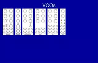
1.6 fOSC drops by 20% in 180-nm VCO due to lack of parasitic extraction tools 8 2 Nf does not scale with L and C at very high frequency because of parasitic gate and source resistances VCO Test Structures
10-GHz Colpitts VCO Tuning range: 9.2 – 10.4GHz (11.8%) Record phase noise: -117.5dBc/Hz @ 1MHz (100 avg.)
77-GHz Colpitts VCO Record tuning range: 73.8 – 80.0GHz (8.3%) Record phase noise: -100.3dBc/Hz @ 1MHz (100 avg.) 20log(8) ≈ 17dB higher than 10-GHz VCO’s phase noise!
10-GHz Cross-coupled VCO Tuning range: 9.3 – 10.9GHz (15.8%) Phase noise: -109.2dBc/Hz @ 1MHz (100 avg.)
77-GHz CMOSCross-coupled VCOs First VCO with p-MOSFET at 77GHz
0.40mm 0.16mm 0.27mm 0.08mm 0.22mm 0.42mm 0.37mm 0.22mm Die Photos 77GHz Cross-coupled VCO: 77GHz Colpitts VCO:
Topology Comparison At very high frequency… At low frequency: ․ √ ․ √ √ √ √ X √ ․ √ X √ ․ √ X
VCO Figure of Merit • Figure of Merit for VCO defined in ITRS 2003: • But, output power is important for mixer, PA…
FoMs Comparison • With FoM2, SiGe HBT VCOs show better performance than CMOS VCOs at mm-wave frequencies
Summary • VCOs with record-breaking performances achieved by algorithmic design at 10 and 77GHz • Frequency scaling of Colpitts VCOs from 10 to 77GHz in 90-nm CMOS, 20 to 40GHz in 180-nm CMOS demonstrated • First cross-coupled VCO with p-MOSFET at 77 GHz • Colpitts topology exhibits better performances than cross-coupled topology at mm-wave frequencies
Acknowledgement • NORTEL and CMC for fabrication • CMC for CAD tools • CFI and OIT for test equipment • Dr. M. T. Yang for support
Loss at Very High Frequency Considering the transistor’s resistance: RG, RS increase with frequency and both lumped to RTANK • Larger transistor size required at very high frequencies It is critical to keep the VCO layout identical: • Transistor layout • Component orientation • Interconnect routing such that layout parasitics also scale