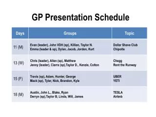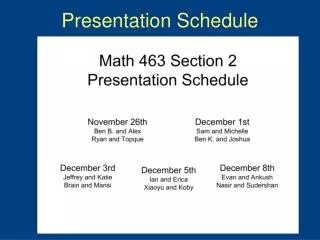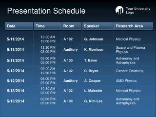
Presentation Schedule
Presentation Schedule. Revised Sept.21 2010. Introduction Student info Sensor info Device info Communication RoboAL3 RoboAL4 References. Introduction. Experiences Started to working for University of Ottawa in 1986 15 years with University of Ottawa Haz- Mat Team

Presentation Schedule
E N D
Presentation Transcript
Presentation Schedule Revised Sept.21 2010 • Introduction • Student info • Sensor info • Device info • Communication • RoboAL3 • RoboAL4 • References
Introduction Experiences • Started to working for University of Ottawa in 1986 • 15 years with University of Ottawa Haz- Mat Team • 10 years with Clarence-Rockland Fire Dept.
Student info. • % of lab marks can be deducted if rules and regulation are not followed ex: by not cleaning up your bench or sliding your chairs back underneath bench top. • Students are responsible for their own extra parts ex: if you want to add a sensor or device that the dept. doesn’t have you are responsible for the purchase and delivery of that part, on rare occasion did the school purchase those parts. • Back packs off bench tops • TA’s will have student # based on station # • Important issue regarding the design of a new project is to do a current analysis before the start of your design
Setup a leader among your team so that you are better organized. • Do not wait before starting your project, start now ! • Prepare yourself before coming to the lab. • It doesn’t work ! Ask yourself if it is software or hardware, use the scope to trouble shoot your problems. • Fuses keeps on blowing, do not replace with lager one. • Do not cut any servo, battery and other device connectors. If you must please come and see me first. • No design must exceed 50 volts, ex: do not work with 120 volts AC. • I can give you what I have regarding metal, wood and plastic recycled pieces and do some cuts or holes with my band saw and drill press for you. • PLEASE DO NOT ask to barrow my own personal tools. If you need to do a task with a special tool that I have then I shall do it for you. You can purchase inexpensive tools from Dollar store
High power class I Blue Tooth TRENDnet TBW-102UB User manual at http://www.trendnet.com/en/products/TBW-102UB.htm
Proper instrumentation settings Oscilloscope
Sensors Sonar Polaroid 6500 (Long Range) www.acroname.com Uses TOF (time of flight) technology Accurate range 15 cm – 10 m Function is to bring high the “init” signal (ping) and then measure the elapsed time until TOF, “echo” signal goes high The “echo” output is an open collector therefore use 4.7 K pull up resistor between the output “echo” and Vcc. May require a 1000 micro farad electrolytic Cap at 50 Volts Install a 0.1 micro farad capacitor in C7 on the board a must have Caution ! 200 Volts p-p on transducer leads
Ultrasonic Ranger SRF04 (Mid Range) www.acroname.com Also uses TOF Range is 3 cm- 3 m Logic lines used to trigger the pulse and echo Compact, perfect for robot applications
Sharp GP2D02 IR (Short Range) www.acroname.com Uses triangulation theory for output results Range 10 cm – 80 cm 8 bit serial output Has a position sensitive detector (PSD) Wiring identification Vout: yellow, Vcc: Red, Vin: Green , Gnd: Black Use diode 1N914 Vin: anode, output: cathode to FPG/HC12 etc.
Single Chip Rate Gyro ADXRS300EB • Used extensively to sense angular rate or rate of rotation. • Plus or minus 300 degrees per second • Analog device • www.analog.com
Vti sca1000 accelerometer • 2-axis measurement; X-Y measurement and Z-Y measurement • Measuring range ±1.7g,±4g • Interchangeable with SCA610/620 • SPI compatible digital output • Internal temperature sensor, accessible via SPI • Qualified according to AEC Q-100
Devantech Digital Compass www.acroname.com 3-4 degrees of accuracy Output PWM (1 ms to 37 ms) Uses Philips KMZ51 magnetic field sensor Wiring identification Pin0:Gnd, Pin1:5v, Pin4: PWM output
Sensor type = Reflective IR • IR sensor = Combined IR LED and detector • I/O required = Three digital lines (inputs) • Minimum range = Almost touching the floor • Maximum range = 1/2" from floor • Input voltage = 5vdc regulated • Current requirements = 50-65mA • PC board size = 2.3" x .75" Optic Sensor TRA-01 (line tracker)
+5 Voltage regulators • T0220 package rated at 1 amp • Pin1: input, Pin2:Gnd Pin3:output • T03 package rated at 3 amps Temperature sensor (Newark part # 50F7748) 4.7 k ohms at room temperature Sensitive to the touch
Hamamastu P5587 Photo reflector • Fast TTL output • Miniature package • Only 12 mA, current draw • Incremental wheel encoders • 64 increments • 5.6 degrees per increments • self adhesive • 3.3 cm in diameter
Devices Futaba FP-S148 Servo Motors • Uses PWM • Freq. is 33 Hz • Range limits 2.2 ms – 0.8 ms with a stop time of 1.26 ms on average • 42 oz-in of torque • Voltage input 4 – 8 Vdc • Wiring identification Vcc: red, Control: white, Gnd: black • Note: Do not exceed 33 Hz motor will be damaged as a result !
Communication Blue tooth class II (MCB3100)www.drrobot.com • Class 2 Bluetooth compatible • On-board communication stack • Effective range: 15 meters indoor, 45 meters outdoor • Support UART data rate: 921.6/460.8/115.2kbps • Serial interface MCR3210P • 1 M bits/sec data rate • RTS/CTS handshaking • Single 3.3 V power supply • 9-pin DSUB connector as DTE
Blue Tooth class I MCB3101 www.drrobot.com • Output Interface UART • Compliant Bluetooth Specification v1.1 • Transmission Power Class 1 (max 18dBm) • Receiving Signal Range -84 to -20dBm • Effective range: 120 meters (Default Antenna)
The ZeroG 802.11 PICtail Plus Daughter Board is a demonstration board for evaluating Wi-Fi connectivity using PIC microcontrollers and the ZeroG ZG2100M module. This product is compatible with the Explorer 16 Development Board and other Microchip development platforms with the PICtail/PICtail Plus connector
XBee Starter kit XB24-DKS Performance Indoor/Urban range: Up to 100 ft (30 m) Outdoor/RF line-of-sight range: up to 300 ft (100 m) RF data rate: 250 Kbps Interface data rate: Up to 115.2 Kbps Operating frequency: 2.4 GHz Receiver sensitivity: -92 dBm Power Supply voltage: 2.8 - 3.4 V Transmit current: 45 mA (@ 3.3 V) Receive current: 50 mA (@ 3.3 V) Power-down sleep current: <10 µA General Frequency band: 2.4000 - 2.4835 GHz Serial data interface: 3V CMOS UART - No configuration required Physical Properties Size: 0.960 in x 1.087 in (2.438 cm x 2.761 cm) Weight: 0.10 oz (3g) - w/ U.FL. connector http://www.digi.com/products/wireless/point-multipoint/xbee-series1-module.jsp
Devantech SP03 Speech Synthesizer module www.acroname.com • Serial interface • Built in speaker • Stores up to 30 phrases (up to 1925 characters total) • PIC processor for easy communication • Winbond WTS701 speech chip • I2C bus interface and parallel interface (I2C: 2 wire bi-directional serial bus)
RFID Reader & Programmer • Read/write ISO15693 RFID Tags • Read ISO14443A RFID Tags • Operates at 13.25MHz • Anti-collision, continuous read and Quiet features • Serial port connection to PC. Suitable for use with USB adapters • Power requirements: 6-9VDC PSU with barrel connector or 5V direct input • Antenna detector to detect RF signal strength • API software for easy integration with your own programs • VB.net Project example • Extensive Documentation on CD http://www.kanda.com
Altera FPGA DE2 interfaces Camera Terasic TRDB-DC2 LCD display Terasic TRDB-LCM http://www.terasic.com.tw/cgi-bin/page/archive.pl?Language=English&CategoryNo=39&No=50
CMUCAM2-CMUCAM2+ CAMERA www.seattlerobotics.com • Track user defined color blobs at up to 50 fps • Track motion using frame differencing at 26 fps • Find the centroid of any tracking data • Gather mean color and variance data • Gather a 28 bin histogram of each color channel • Manipulate horizontal pixel differenced images • Arbitrary image windowing • Adjust the camera’s image properties • Dump a raw image • Up to 160 X 255 resolution • Support multiple baud rates • Control 5 servos outputs • Slave parallel image processing mode off of single camera bus • Automatically use servos to do two axis color tracking • B/W analog video output (Pal or NTSC) • Flexible output packet customization • Multiple pass image processing on a buffered image
Altera Cyclone board • Nios embedded processor • Cyclone EP1C20 device • 10/100 Ethernet on board • CompactFlash • Two UART Connectors • 1 Mbyte SRAM, 16 Mbyte SDRAM, 8 Mbyte Flash Memory • Quartus II Design software with SOPC builder
Altera DE2 • Altera Cyclone II (2C35) FPGA with 35,000 LE’s • 16 Mbite serial configuration device • Built-in USB Blaster • TV Decoder for NTSC/PAL Multiformat system • 24 bit CD quality Audio CODEC • VGA DAC (10 bit DAC) • USB Host and Device • Ethernet 10/100 Mbps • SRAM,SDRAM,Flash,SD Card connector • RS-232, IrDA,PS/2 • 16X2 LCD Panel
Motorola Adapt9S12DP256 Microcontroller board • Two 50 pin connectors bring out all I/O pins of the MCU • RS-232 transceiver provide for both SCI channels • 16 Mhz crystal, but internal bus can run up to 24 Mhz • Accommodates optional user supplied oscillator • Back ground debug Mode • Program in C, Basic, and Assembler, etc..
Microchip Explorer 16 Development Board Features• Includes PIC24FJ128GA010 and the dsPIC33FJ256GP710 DSC DigitalSignal Controller PIMs (100-pin version) or the PIC24FJ64GA004 PIM (44-pin version).• Alpha-numeric 16 x 2 LCD display• Interfaces to MPLAB ICD 2, MPLAB REAL ICE, USB, and RS-232• Includes Microchip's TC1047A high accuracy, analog output temperature sensor• Expansion connector to access full devices pin-out and bread board prototyping area
MICROCHIP PICkit microcontroller • Easy low cost way to start development • Uses selected Flash-base PIC microcontrollers • MPLAB IDE Software • USB interface • www.microchip.com
Arduino Duemilanove New Overview The Arduino Duemilanove ("2009") is a microcontroller board based on the ATmega168 (datasheet) or ATmega328 (datasheet). It has 14 digital input/output pins (of which 6 can be used as PWM outputs), 6 analog inputs, a 16 MHz crystal oscillator, a USB connection, a power jack, an ICSP header, and a reset button. It contains everything needed to support the microcontroller; simply connect it to a computer with a USB cable .
WiFi shield • Provides Wi-Fi connectivity to your Arduino-based project• Uses SPI for host communication (max speed 25MHz)• 16Mbit serial flash for storing web pages and other data• External antenna Summary Microcontroller ATmega328 Operating Voltage 5V Input Voltage (recommended) 7-12V Digital I/O Pins 14 (of which 6 provide PWM output) Analog Input Pins 6 DC Current per I/O Pin 40 mA (do not exceed) DC Current for 3.3V Pin 50 mA (do not exceed) Flash Memory 32 KB (ATmega328) of which 2 KB used by bootloader SRAM 2 KB (ATmega328) EEPROM 1 KB (ATmega328)
New tools Apple Iphone 3G 16 Gig Apple IMac 20”
RoboAl3 Features • Altera’s Cyclone board (EP1C20) with LCD display • Cmucam 2+ with pan and tilt turret • Powerful solenoid, shoot puck 2 feet an average with aprox. 200 shots note: do not leave plunger out, it will damage the internal coil • Differential steering using two servo motors, Futaba FP-S148 • Powered by 2 NiCad 1700 mA/h batteries and AC adaptor controlled by selector switch. Dual in lab battery chargers. note: you can charge both batteries at the same time while still mount underneath robot • New photo reflector circuit, using Hamamastu photo reflector P5587 with wheel incremental encoders (64 increments for 360 degrees therefore 5.6 degrees per increments • Two prototyping bread boards 2 X 6.5 inches • Front puck holding guide • Female board mount sockets, use 22 gauge solid wire only. • Powerful 3000 mA regulator • Blue tooth class II MCB3100 with serial interface MCR3210P
Roboal4 Features • Altera’s Cyclone board (EP1C20) with LCD display • Cmucam 2 with pan and tilt turret • Differential steering using two servo motors, Futaba FP-S148 • Powered by 2 NiCad 1700 mA/h batteries and AC adaptor controlled by selector switch. Dual in lab battery chargers. note: you can charge both batteries at the same time while still mount underneath robot • New photo reflector circuit, using Hamamastu photo reflector P5587 with wheel incremental encoders (64 increments for 360 degrees therefore 5.6 degrees per increments • Two prototyping bread boards 2 X 6.5 inches • Female board mount sockets, use 22 gauge solid wire only. • Powerful 3000 mA regulator • Blue tooth class II MCB3100 with serial interface MCR3210P
Entrepreneurship and Innovation Endowment FundUniversity of Ottawa - Faculty of Engineering • http://www.eng.uottawa.ca/eng/eief/index.php
References • Photo’s ,Text and Schematics Information • www.acroname.com • www.lynxmotion.com • www.drrobot.com • www.analog.com • www.microchip.com • www.vti.com • www.technologicalarts.com Presentation version: Jan 12 2010