Business Process Modeling Essentials with Activity Diagrams
900 likes | 995 Vues
Learn the rules and style guidelines for creating activity diagrams, use cases, and use case diagrams for functional modeling. Understand processes to create use cases and diagrams, and use use case points effectively. Explore how activity diagrams model behavior, data flow, and parallel activities in business processes.

Business Process Modeling Essentials with Activity Diagrams
E N D
Presentation Transcript
Systems Analysis and Design with UML Version 2.0, Second Edition Chapter 6: Functional Modeling
Objectives ■ Understand the rules and style guidelines for activity diagrams. ■ Understand the rules and style guidelines for use cases and use case diagrams. ■ Understand the process used to create use cases and use case diagrams. ■ Be able to create functional models using activity diagrams, use cases, and use case diagrams. ■ Become familiar with the use of use case points.
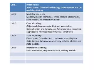
Business Process Modeling with Activity Diagrams Elements of an Activity Diagram Guidelines for Creating Activity Diagrams
BPM With Activity Diagrams • A number of activities support a business process across several departments • Activity diagrams model the behavior in a business process • Sophisticated data flow diagrams • Addresses Parallel concurrent activities and complex processes
Activity Diagrams Activity Diagrams can model: An entire system A Subsystems of a system A subsystem A use case A method
Activity Diagrams Activity diagrams are most helpful in defining subsystems or subprocesses of large systems (We do not hand in activity diagrams as a deliverable in this class.)
Activity Diagrams • Components of the Activity Diagram • Initial node • Activity final node • Activity nodes • Flow/edges • Forks, and Joins • Conditions. Decisions, and Merges • Partitions • Sub-activity indicators • Flow final
NEW Activity Diagram Components Represents the starting node Represents the ending node Activity or action Activity may have 1.M actions Represents objects participating (can be omitted at first) Represents a decision point in flow Represents joining and forking of parallel activities
Creating Activity Diagrams 1. Since an activity diagram is used to model various granularity of processes – FIRST determine the context or scope of the activity being modeled. 2. Identify the initial node and final node to set the context of the scope. • Initial node. The filled in circle is the starting point of the diagram. An initial node isn’t required although it does make it significantly easier to read the diagram. • Activity final node. The filled circle with a border is the ending point. An activity diagram can have zero or more activity final nodes.
Creating Activity Diagrams Place The Initial Node In The Top-Left Corner. A initial node is modeled with a filled in circle. Place The Final Node at the Lower-Right Corner. A final node is modeled with a filled circle inside a clear circle.
Creating Activity Diagrams 3. Identify activity nodes needed in this process being modeled. Activity. The rounded rectangles represent activities that occur within the process being modeled. The example below is a simple enroll in the university use case. It is just a simple way to model this activity.
Creating Activity Diagrams Fill out enrollment forms Get help to fill out forms Enroll in University Attend Orientation Enroll in Seminar Make Tuition Payment Place the activities in a somewhat sequential order of the flow of events within the process being modeled.
Creating Activity Diagrams 4. Connect the activities with flows. Flow/edge. The arrows on the diagram.
Creating Activity Diagrams Fill out enrollment forms Get Help to fill out forms Enroll in University Attend Orientation Enroll in Seminar Make Tuition Payment
Creating Activity Diagrams 5. Add any forks, joins, decisions, ormerges. Fork. A black bar with one flow going into it and several leaving it. This denotes the beginning of parallel activity • Join. A black bar with several flows entering it and one leaving it. All flows going into the join must reach it before processing may continue. This denotes the end of parallel processing. • Decision. A diamond with one flow entering and several leaving. The flows leaving include conditions although some modelers will not indicate the conditions if it is obvious. • Merge. A diamond with several flows entering and one leaving. The implication is that one or more incoming flows must reach this point until processing continues, based on any guards on the outgoing flow.
Creating Activity Diagrams incorrect Fill out enrollment forms Get Help to Fill out forms correct Enroll in University Attend Orientation Make Tuition Payment Enroll in Seminar
Key Ideas • A use case illustrates the activities that are performed by users of a system. • Use cases are logical models -- they describe the activities of a system without specifying how the activities are implemented.
Two Approaches • Approaches to creating the two components of the use case include: • 1. Create the use case description first and from it create the use case diagram. (text approach) • 2. Create the use case diagram first, then create the use case diagram, and revise the diagram if needed after the description is written. (our approach)
What are Use-Case Descriptions? • Describes use cases defined in the use case diagram. • What the user can do • How the system responds • Use cases are building blocks for continued design activities.
Types of Use-Cases • Overview versus detail ■ The use case represents an important business process. ■ The use case supports revenue generation or cost reduction. ■ Technology needed to support the use case is new or risky and therefore will require considerable research. • Essential versus real
Use Case Description Data Dictionary Use Case Documentation Name ID Requirement Number Description Primary Actor Secondary Actor(s) Pre-condition Post-condition Trigger Normal Scenario 1 2 3 4 … Extensions 1 2 3 4 …
Use Case • A major process performed by the system that benefits an actor(s) in some way • Models a dialogue between an actor and the system • Represents the functionality provided by the system
Use Case Diagram • Project team gathers requirements from the users about functionality of the system to be built. • Project team prepare: • Use case diagram • Use case description for each use case in the use case diagram • Analysts create class diagrams.
Elements of a Use-Case Description Use Case Name ID REQ# Description Primary and Secondary Actors: Pre-conditions Post-conditions Trigger Normal scenario Extensions
Use Case Name: ID: Importance Level: Primary Actor: Use Case Type: Stakeholders and Interests: Brief Description: Trigger: Relationships: (Association, Include, Extend, Generalization) Normal Flow of Events: Subflows: Alternate/Exceptional Flows: Elements of a Use-Case Description While there are many variations, our use case description is explained in this weeks lecture.
Use-case Description General Contents for description • Use-case name • should be a verb-noun phrase • ID (ID Number) • REQ# (Requirement Number) • Description • Typically a single sentence that describes the essence of the use case
Use-case Description • Primary actor • Person or thing that starts the execution of the use case • Secondary actor • People who have an interest in the use case • Together often known as “stakeholders”
Pre-condition • The necessary conditions that have to be met before the use case can be performed • When writing a precondition, you are making a simple assertion statement about the current state of the world when this use case opens. • The mistake in writing preconditions is writing something that is often, but not always, true.
Pre-condition Examples • User is logged on. • Customer has been validated. • The system has already located the customer’s policy information.
Post-conditions • The state of the system after the use case is performed • The value delivered to the actor • These statements state what interests that are satisfied after a successful conclusion of the use case.
Triggers • Specifies the event that gets the use case started. • It precedes the first step of the scenario.
Examples of Triggers • Trigger: Customer inserts card. • Trigger: Customer calls in complaint.
Normal Scenario • Path that an end user is mostly likely to follow • Goal is to satisfy the stakeholders’ interests
Normal Scenario • Every scenario is written as a sequence of goal-achieving actions of the various actors. • 3 kinds of action steps: • An interaction between two actors • A validation step to protect an interest of a stakeholder • An internal change to satisfy an interest of a stakeholder
Normal Scenario • Clerk enters insured’s policy number or else name and date of incident. • System populates available policy information and indicates claim is matched to policy. • Clerk enters basic loss information. • System confirms there are no competing claims and assigns a claim number. • Clerk continues entering loss information specific to claim line. • Clerk has System pull other coverage information from other computer systems. • Clerk selects and assigns an Adjuster. • Clerk confirms he/she is finished. • System saves and triggers acknowledgement to be sent to Agent.
Normal Scenario • Each statement is written to show a simple, active action. • These statements are written as a soccer match: • Person 1 kicks ball to person 2 • Person 2 dribbles ball • Person 2 kicks ball to person 3
Write each step in “SVDPI” form Clarify initiator and receivers of action (actors involved) Try to keep each step at the same level of abstraction Ensure a sensible set of steps Apply KISS principle liberally Write repeating instructions after the set of steps to be repeated. Heuristics
Guidelines: Action Steps • Show clearly “Who Has the Ball” • Establish at all times who has possession of the statement (who has the ball) • Example: • Customer puts in the ATM Card.
Guidelines: Action Steps • Write from a bird’s eye view • Do not write as the system looking out to the world, rather write as an onlooker to the system.
Guidelines: Action Steps • Write from a bird’s eye view • Example: • (Bad) Get ATM Card and PIN number. • (Good) The customer puts in the ATM card and PIN. • Example: • (Bad) Deduct amount from account balance. • (Good) The system deducts the amount from the account balance.
Guidelines: Action Steps • Show the process moving forward • Do not make the use case lengthy • Typically a use case should be no longer than 9 actions steps in the primary scenario • If there is a problem decreasing the length of the statement, ask “Why is the actor doing that?”
Guidelines: Action Steps • Show the actor’s intent, not the movements • Bad example: • System asks for name. • User enters name. • System prompts for address. • User enters address. • User clicks “OK’. • System presents user’s profile.
Guidelines: Action Steps • Show the Actor’s Intent, Not the Movements • Good example: • User enters name and address. • System presents user’s profile.
Guidelines: Action Steps • Include a “Reasonable” Set of Actions • Transactions have four parts: • Primary actor sends request and data to system • System validates request and the data • The system alters its internal state • The system responds to the actor with the result.
Guidelines: Action Steps • “Validate”; don’t “check whether” • Don’t state in an action step “Check Whether” • Use an affirmative statement “Validates” • If you check whether, the next statement typically has an if condition statement following.
Guidelines: Action Steps • “Validate”; don’t “check whether” • Bad example: • The system checks whether the password is correct. • If it is, the system presents the available actions for the user. • Good example: • The system validates that the password is correct. • The system presents the available actions for the user.
Guidelines: Action Steps • Optionally mention the timing • Timing typically is obvious and doesn’t need to be mentioned; however, there may be a time that it does need to be mentioned • As soon as the user has…the system will… • At any time between steps 3 and 5, the user will…