Measuring Airglow Emissions at 100 km: Advancing Low-Cost Earth Sensors
This project aims to measure airglow emissions in the upper atmosphere at an altitude of 100 km. We seek to demonstrate the feasibility of using airglow as a low-cost Earth sensing mechanism. The objectives include validating existing airglow models and enhancing our understanding of airglow's dependence on latitude, altitude, and local solar time. Our instrument will observe emissions at 762 nm with specific design requirements for resolution and power, ensuring resilience against sun exposure. The findings could support innovative Earth observation technologies.

Measuring Airglow Emissions at 100 km: Advancing Low-Cost Earth Sensors
E N D
Presentation Transcript
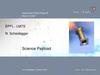
EPFL - LMTSN. Scheidegger Science Payload
Science Objectives Measure the airglow emission in the upper atmosphere at 100 km altitude to : • Demonstrate the feasibility of using airglow as a basis for a low-cost Earth Sensor • Validate the established airglow model or bring additional information about airglow dependence on → latitude→ altitude→ local solar time Nightglow and aurora borealis
Expected airglow at 700 km altitude Airglow [photons/pixel/s] * *for an aperture of Ø4 mm and a FOV of 0.16°/pixel = minimum photon flux
Driving Requirements • Payload may be a technology demonstrator of the Earth Sensor based on airglow • Observes the emission at 762 nm with a bandwidth of at least [10] nm • Has a spatial resolution of at least [0.3]° and a FOV of at least [20]° • Observes the airglow with a CMOS SPAD array if possible • Survives having its boresight directly sun pointing for a period of at least 10 hours • Can perform science mission with the sun no closer than [30]° from its boresight. • Physical constraints • Volume: [30 x 30 x 70] mm3 for optics and detector [70 x 30 x 20] mm3 for mainboard • Mass: [60] g • Power: [450] mW, during [10]s for each image
Science Payload Instrument Design headboard mainboard baffle filter detector optical system
Design Description • Detector and control electronics • Detect photons and generate digital output which is proportional to local light intensity • Provides required power and control signal for the detector • Interfaces with CDMS and ground station • Optical system • Magnifies the image • Filters the selected airglow line • Protects detector from sun • Links the detector mechanically to the satellite bus
Detector * for an aperture of Ø4 mm and a total FOV of 25° for a SPAD array = current baseline design † including a Binning of 4 x 4 pixels
Diploma project: Design of a Telescope for the SwissCube Picosatellite • Understanding of the science and project requirements on the payload • Optical design for the payload • Opto-mechanical design for the payload, including selection of material for lens and support structure • Assembly of the overall payload subsystem based on the CMOS detector • Testing and verification of the optical properties of the payload • Documentation, preparation of end-of-phase review. • (Electrical design for the CMOS detector control) • (Establishment of hardware, data flow and cabling block diagrams for the payload subsystem, including connection with the other subsystems) • (Testing and verification of the electrical, power and sensitivity performance of the detector)
My inputs: • Filter design (1.5.07) • Determination of the interface with the CDMS sub-system (1.4.07) • (Electrical design for the CMOS detector control) (1.5.07) • (Establishment of data flow and cabling block diagrams for the payload subsystem, including connection with the other subsystems) (1.5.07)
Planned meetings and reports: • 1 x per month with the whole payload subsystem team • Every week: each student reports briefly his/her last analyses and results (1 A4 page)
CDMS – Payload Interface • PL microcontroller: • Guarantees a standard interface between the detector and the CDMS subsystem or commands coming from the ground station • CDMS subsystem: • Controls activation of the payload subsystem • Provides the parameters for the detector initialization (integration time, binning factor, DCR suppression factor,…) • Reads the science data directly form the detector • Does image compression if necessary • Formats science data according to the science data product • Stores the science data until transfer to the ground station