Exploring Shaders: The Magic Behind Graphics Processing and Custom Effects
This lecture by Alex Benton from the University of Cambridge delves into the intricacies of shaders—programmable units in the GPU that revolutionize graphics processing. Understanding local and world space transformations, vertex processing, and pixel plotting is crucial. The lecture covers shader types, how they communicate through parameters, and the flexibility they provide for user-generated code. With examples using HLSL, GLSL, and Cg, attendees will gain insights into how shaders enable custom graphics effects, making visual experiences richer and more dynamic.

Exploring Shaders: The Magic Behind Graphics Processing and Custom Effects
E N D
Presentation Transcript
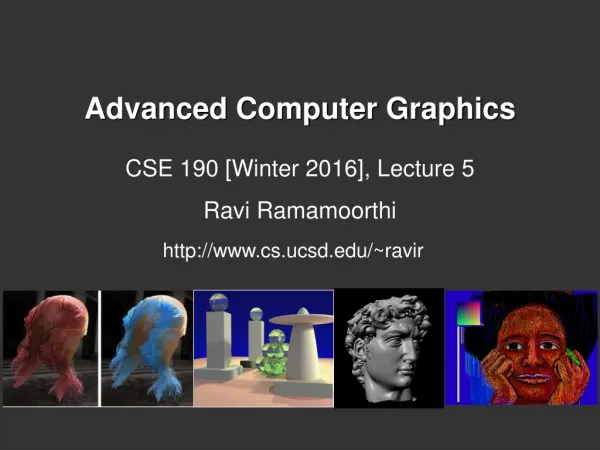
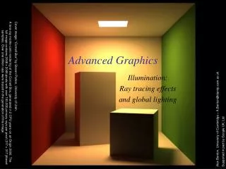
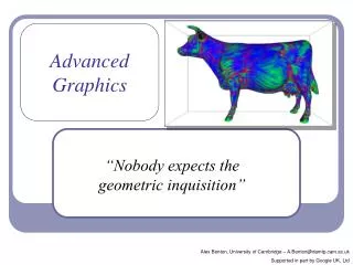
Advanced Graphics “The Shader knows…” Alex Benton, University of Cambridge – A.Benton@damtp.cam.ac.uk Supported in part by Google UK, Ltd
Local space World space Viewing space 3D screen space Process vertices Clipping, projection, backface culling Process pixels 2D display space – plot pixels Closer to the truth (but still a terrible oversimplification) What is… the shader? Local space World space Viewing space 3D screen space 2D display space Last lecture…
Ex: computing diffuse shading color per vertex; transforming vertex position; transforming texture co-ordinates “Wouldn’t it be great if the user could install their own code into the hardware to choose these effects?” Ex: interpolating texture coordinates across the polygon; interpolating the normal for specular lighting; textured normal-mapping What is… the shader? Local space World space Viewing space Local space 3D screen space World space Process vertices Viewing space Clipping, projection, backface culling 3D screen space Process pixels 2D display space 2D display space – plot pixels Last lecture… Closer to the truth (but still a terrible oversimplification)
What is… the shader? • The next generation: Introduce shaders, programmable logical units on the GPU which can replace the “fixed” functionality of OpenGL with user-generated code. • By installing custom shaders, the user can now completely override the existing implementation of core per-vertex and per-pixel behavior.
Shader gallery I Above: Demo of Microsoft’s XNA game platform Right: Product demos by nvidia (top) and Radeon (bottom)
What are we targeting? • OpenGL shaders give the user control over each vertex and each fragment (each pixel or partial pixel) interpolated between vertices. • After vertices are processed, polygons are rasterized. During rasterization, values like position, color, depth, and others are interpolated across the polygon. The interpolated values are passed to each pixel fragment.
Per vertex: Vertex transformation Normal transformation and normalization Texture coordinate generation Texture coordinate transformation Lighting Color material application Per fragment (pixel): Operations on interpolated values Texture access Texture application Fog Color summation Optionally: Pixel zoom Scale and bias Color table lookup Convolution What can you override?
Think parallel • Shaders are compiled from within your code • They used to be written in assembler • Today they’re written in high-level languages () • They execute on the GPU • GPUs typically have multiple processing units • That means that multiple shaders execute in parallel • We’re moving away from the purely-linear flow of early “C” programming models
Least advanced; most portable and supported; topic of this lecture. What’re we talking here? • There are several popular languages for describing shaders, such as: • HLSL, the High Level Shading Language • Author: Microsoft • DirectX 8+ • Cg • Author: nvidia • GLSL, the OpenGL Shading Language • Author: the Khronos Group, a self-sponsored group of industry affiliates (ATI, 3DLabs, etc)
OpenGL programmable processors (not to scale) Figure 2.1, p. 39, OpenGL Shading Language, Second Edition, Randi Rost, Addison Wesley, 2006. Digital image scanned by Google Books.
Vertex processor – inputs and outputs Color Normal Position Texture coord etc… Vertex Processor Color Position Texture data Custom variables Modelview matrix Material Lighting etc… Custom variables Per-vertex attributes
Fragment processor – inputs and outputs Color Texture coords Fragment coords Front facing Fragment Processor Fragment color Fragment depth Texture data Modelview matrix Material Lighting etc… Custom variables
How do the shaders communicate? There are three types of shader parameter in GLSL: • Uniform parameters • Set throughout execution • Ex: surface color • Attribute parameters • Set per vertex • Ex: local tangent • Varying parameters • Passed from vertex processor to fragment processor • Ex: transformed normal Attributes Vertex Processor Uniform params Varying params Fragment Processor
What happens when you install a shader? • All the fixed functionality (see slide six) is overridden. • It’s up to you to replace it! • You’ll have to transform each vertex into viewing coordinates manually. • You’ll have to light each vertex manually. • You’ll have to apply the current interpolated color to each fragment manually. • The installed shader replaces all OpenGL fixed functionality for all renders until you remove it.
Shader gallery II Above: Kevin Boulanger (PhD thesis, “Real-Time Realistic Rendering of Nature Scenes with Dynamic Lighting”, 2005) Above: Ben Cloward (“Car paint shader”)
Shader sample one – ambient lighting // Vertex Shader void main() { gl_Position = gl_ModelViewProjectionMatrix * gl_Vertex; } // Fragment Shader void main() { gl_FragColor = vec4(0.2, 0.6, 0.8, 1); }
Shader sample one – ambient lighting • Notice the C-style syntax • void main() { … } • The vertex shader uses two standard inputs, gl_Vertex and the model-view-projection matrix; and one standard output, gl_Position. • The line gl_Position = gl_ModelViewProjectionMatrix * gl_Vertex; applies the model-view-projection matrix to calculate the correct vertex position in perspective coordinates. • The fragment shader applies basic ambient lighting, setting its one standard output, gl_FragColor, to a fixed value.
// Vertex Shader varying vec3 Norm; varying vec3 ToLight; void main() { gl_Position = gl_ModelViewProjectionMatrix * gl_Vertex; Norm = gl_NormalMatrix * gl_Normal; ToLight = vec3( gl_LightSource[0].position - (gl_ModelViewMatrix * gl_Vertex)); } // Fragment Shader varying vec3 Norm; varying vec3 ToLight; void main() { const vec3 DiffuseColor = vec3(0.2, 0.6, 0.8); float diff = clamp(dot(normalize(Norm), normalize(ToLight)), 0.0, 1.0); gl_FragColor = vec4(DiffuseColor * diff, 1.0); } Shader sample two – diffuse lighting
Shader sample two – diffuse lighting • This examples uses varying parameters to pass info from the vertex shader to the fragment shader. • The varying parameters Norm and ToLight are automatically linearly interpolated between vertices across every polygon. • This represents the normal at that exact point on the surface. • The exact diffuse illumination is calculated from the local normal. • This is the Phong shading technique (usually seen for specular highlights) applied to diffuse lighting.
Shader sample two – diffuse lighting • Notice the different matrix transforms used in this example: gl_Position = gl_ModelViewProjectionMatrix * gl_Vertex; Norm = gl_NormalMatrix * gl_Normal; ToLight = vec3(gl_LightSource[0].position - (gl_ModelViewMatrix * gl_Vertex)); • The gl_ModelViewProjectionMatrix transforms a vertex from local coordinates to perspective coordinates for display, whereas the gl_ModelViewMatrix transforms a point from local coordinates to eye coordinates. We use eye coordinates because lights are (usually) defined in eye coordinates. • The gl_NormalMatrix transforms a normal from local coordinates to eye coordinates; it holds the inverse of the transpose of the upper 3x3 submatrix of the model-view transform.
GLSL – design goals • GLSL was designed with the following in mind: • Work well with OpenGL • Shaders should be optional extras, not required. • Fit into the design model of “set the state first, then render the data in the context of the state” • Support upcoming flexibility • Be hardware-independent • The GLSL folks, as a broad consortium, are far more invested in hardware-independence than, say, nvidia. • That said, they’ve only kinda nailed it: I get different compiler behavior and different crash-handling between my high-end home nVidia chip and my laptop Intel x3100. • Support inherent parallelization • Keep it streamlined, small and simple
GLSL • The language design in GLSL is strongly based on ANSI C, with some C++ added. • There is a preprocessor--#define, etc! • Basic types: int, float, bool • No double-precision float • Vectors and matrices are standard: vec2, mat2 = 2x2; vec3, mat3 = 3x3; vec4, mat4 = 4x4 • Texture samplers: sampler1D, sampler2D, etc are used to sample multidemensional textures • New instances are built with constructors, a la C++ • Functions can be declared before they are defined, and operator overloading is supported.
GLSL • Some differences from C/C++: • No pointers, strings, chars; no unions, enums; no bytes, shorts, longs; no unsigned. No switch() statements. • There is no implicit casting (type promotion): float foo = 1; fails because you can’t implicitly cast int to float. • Explicit type casts are done by constructor: vec3 foo = vec3(1.0, 2.0, 3.0); vec2 bar = vec2(foo); // Drops foo.z • Function parameters are labeled as in (default), out, or inout. • Functions are called by value-return, meaning that values are copied into and out of parameters at the start and end of calls.
The GLSL API To install and use a shader in OpenGL: • Create one or more empty shader objects with glCreateShader. • Load source code, in text, into the shader with glShaderSource. • Compile the shader with glCompileShader. • The compiler cannot detect every program that would cause a crash. (And if you can prove otherwise, see me after class.) • Create an empty program object with glCreateProgram. • Bind your shaders to the program with glAttachShader. • Link the program (ahh, the ghost of C!) with glLinkProgram. • Register your program for use with glUseProgram. Vertex shader Fragment shader Program Compiler Linker OpenGL
// From the Orange Book varying float NdotL; varying vec3 ReflectVec; varying vec3 ViewVec; void main () { vec3 ecPos = vec3(gl_ModelViewMatrix * gl_Vertex); vec3 tnorm = normalize(gl_NormalMatrix * gl_Normal); vec3 lightVec = normalize(gl_LightSource[0].position.xyz - ecPos); ReflectVec = normalize(reflect(-lightVec, tnorm)); ViewVec = normalize(-ecPos); NdotL = (dot(lightVec, tnorm) + 1.0) * 0.5; gl_Position = ftransform(); gl_FrontColor = vec4(vec3(0.75), 1.0); gl_BackColor = vec4(0.0); } vec3 SurfaceColor = vec3(0.75, 0.75, 0.75); vec3 WarmColor = vec3(0.1, 0.4, 0.8); vec3 CoolColor = vec3(0.6, 0.0, 0.0); float DiffuseWarm = 0.45; float DiffuseCool = 0.045; varying float NdotL; varying vec3 ReflectVec; varying vec3 ViewVec; void main() { vec3 kcool = min(CoolColor + DiffuseCool * vec3(gl_Color), 1.0); vec3 kwarm = min(WarmColor + DiffuseWarm * vec3(gl_Color), 1.0); vec3 kfinal = mix(kcool, kwarm, NdotL) * gl_Color.a; vec3 nreflect = normalize(ReflectVec); vec3 nview = normalize(ViewVec); float spec = max(dot(nreflect, nview), 0.0); spec = pow(spec, 32.0); gl_FragColor = vec4(min(kfinal + spec, 1.0), 1.0); } Shader sample three – Gooch shading
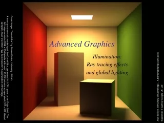
Shader sample three – Gooch shading • Gooch shading is not a shader technique per se. • It was designed by Amy and Bruce Gooch to replace photorealistic lighting with a lighting model that highlights structural and contextual data. • They use the diffuse term of the conventional lighting equation to choose a map between ‘cool’ and ‘warm’ colors. • This is in contrast to conventional illumination where diffuse lighting simply scales the underlying surface color. • This, combined with edge-highlighting through a second renderer pass, creates models which look more like engineering schematic diagrams. Image source: “A Non-Photorealistic Lighting Model For Automatic Technical Illustration”, Gooch, Gooch, Shirley and Cohen (1998). Compare the Gooch shader, above, to the Phong shader (right).
Shader sample three – Gooch shading • In the vertex shader source, notice the use of the built-in ability to distinguish front faces from back faces: gl_FrontColor = vec4(vec3(0.75), 1.0); gl_BackColor = vec4(0.0); This supports distinguishing front faces (which should be shaded smoothly) from the edges of back faces (which will be drawn in heavy black.) • In the fragment shader source, this is used to choose the weighted diffuse color by clipping with the a component: vec3 kfinal = mix(kcool, kwarm, NdotL) * gl_Color.a; Here mix() is a GLSL method which returns the linear interpolation between kcool and kwarm. The weighting factor (‘t’ in the interpolation) is NdotL, the diffuse lighting value.
Antialiasing on the GPU • Hardware antialiasing can dramatically improve image quality. • The naïve approach is simply to supersample the image • This is easier in shaders than it is in standard software • But it really just postpones the problem. • Several GPU-based antialiasing solutions have been found. • Eric Chan published an elegant polygon-based antialiasing approach in 2004 which uses the GPU to prefilter the edges of a model and then blends the filtered edges into the original polygonal surface. (See figures at right.)
Antialiasing on the GPU • One clever form of antialiasing is adaptive analytic prefiltering. • The precision with which an edge is rendered to the screen is dynamically refined based on the rate at which the function defining the edge is changing with respect to the surrounding pixels on the screen. • This is supported in the shader language by the methods dFdx(F) and dFdy(F). • These methods return the derivative with respect to X and Y of some variable F. • These are commonly used in choosing the filter width for antialiasing procedural textures. (A) Jagged lines visible in the box function of the procedural stripe texture (B) Fixed-width averaging blends adjacent samples in texture space; aliasing still occurs at the top, where adjacency in texture space does not align with adjacency in pixel space. (C) Adaptive analytic prefiltering smoothly samples both areas. Image source: Figure 17.4, p. 440, OpenGL Shading Language, Second Edition, Randi Rost, Addison Wesley, 2006. Digital image scanned by Google Books. Original image by Bert Freudenberg, University of Magdeburg, 2002.
Particle systems on the GPU • Shaders extend the use of texture memory dramatically. Shaders can write to texture memory, and textures are no longer limited to being a two-dimensional plane of RGB(A). • A particle systems can be represented by storing a position and velocity for every particle. • A fragment shader can render a particle system entirely in hardware by using texture memory to store and evolve particle data. Image by Michael Short
Particle systems with shaders Slide 17 of Lutz Latta’s “Everything About Particle Effects”, delivered at the Game Developers Conference ’07 (San Francisco).
Subdivision surfaces on the GPU • Several techniques now exist for doing subdivision surface on the GPU. • An early approach by Boubekeur and Schlick used a predefined ‘generic’ model to subdivide each triangle, then applied a procedural distortion map to the positions of the new vertices. • Later work, such as Castaño’s at nVidia, builds a complete tessellation pipeline in hardware. Boubekeur and Schlick (2005) Castaño (2008)
Ongoing development • Since 2007 nvidia has supported geometry shaders, though standardized acceptance took a while. • Today most shader languages support geometry shaders, which run after the vertex shader and can generate new primitives (vertices, vertex strips, etc.) • Support has been standardized since DirectX 10 and OpenGL 3.2.
CPU vs GPU – an object demonstration “NVIDIA: Adam and Jamie explain parallel processing on the GPU” http://www.youtube.com/watch?v=ZrJeYFxpUyQ
Recap • Shaders give a powerful, extensible mechanism for programming the vertex and pixel processing stages of the GPU pipeline. • GLSL is a portable, multiplatform C-like language which is compiled at run-time and linked into an executable shader program. • Shaders can be used for a long list of effects, from procedural geometry and non-photorealistic lighting to advanced textures, fog, shadows, raycasting, and visual effects; in fact, many of the topics covered in this course! (The first 21 images returned by Google Image Search for “shaders”.)