
GPS C/A CODER
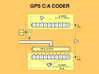
GPS C/A CODER. b = 1 1 0 1 1 0 1 1 0 1 1 0 1 1 0. Repeats 1 2 3 4 5. KASAMI CODE IMPLEMENTATION. X 4 + X + 1 q = 2 n/2 + 1 = 5 m = 2 n/2 - 1 = 3 Where, q = decimation value m = period of a’. a.

GPS C/A CODER
E N D
Presentation Transcript
b = 1 1 0 1 1 0 1 1 0 1 1 0 1 1 0 Repeats 1 2 3 4 5 KASAMI CODE IMPLEMENTATION X4 + X + 1 q = 2n/2 + 1 = 5 m = 2n/2 - 1 = 3 Where, q = decimation value m = period of a’ a a = 1 1 1 1 0 1 0 1 1 0 0 1 0 0 0 a’ = 1 1 0 • a xor b = 0 0 1 0 1 1 1 0 1 1 1 1 1 1 0 • Kasami codes are generated by cyclically shifting a 2n/2 -2 = 2 times • Including a and b there are 2n/2 = 4 sequences
FACTORS FOR DETERMINING SIGNALING FORMAT • Signal spectrum • Synchronization • Interference and noise immunity • Error detection capability • Cost and complexity
DIGITAL SIGNAL ENCODING FORMATS • Biphase-Space Always a transition at beginning of interval • 1 = no transition in middle of interval • 0 = transition in middle of interval • Differential Manchester Always a transition at middle of interval • 1 = no transition at beginning of interval • 0 = transition at beginning of interval • Delay Modulation (Miller) • 1 = transition in middle of interval • 0 = no transition if followed by 1, transition at end of interval if followed by 1 • Bipolar • 1 = pulse in first half of bit interval, alternating polarity from pulse to pulse • 0 = no pulse • Nonreturn to zero-level (NRZ-L) • 1 = high level • 0 = low level • Nonreturn to zero-mark (NRZ-M) • 1 = transition at beginning of interval • 0 = no transition • Nonreturn to zero-space (NRZ-S) • 1 = no transition • 0 = transition at beginning of interval • Return to zero (RZ) • 1 = pulse in first half of bit interval • 0 = no pulse • Biphase-Level (Manchester) • 1 = transition from hi to lo in middle of interval • 0 = transition from lo to hi in middle of interval • Biphase-Mark Always a transition at beginning of interval • 1 = transition in middle of interval • 0 = no transition in middle of interval
Binary Phase Shift Keying (BPSK) Data + Code 1800 Phase Shifts BPSK Carrier
x Σ x x x ~ 900 QPSK BLOCK DIAGRAM m1(t)cos(2πft) Code 1 cos(2πft) Data 1 Carrier SQPSK sin(2πft) Code 2 m2(t)sin(2πft) m2(t) Data 2 SQPSK(t) = m1cos(2πft) + m2sin(2πft) m1(t) Twice the data same BW
x Σ x x ~ 900 ALTERNATIVE IMPLEMENTATION OF QPSK 2-bit serial to parallel Code Data Half the BW same data rate