Download
1 / 76
760 likes | 784 Vues
Huawei SX7 Campus Switches Configuration Quotation Guide ( Overseas). Tools. UniSTAR eCFG Customized Description: Offline quotation tool Training material (channel) UniSTAR SCT Web-based Description: Simplified online quotation tool (only this tool will be provided in future) SCT

E N D
Huawei SX7 Campus Switches Configuration Quotation Guide (Overseas)
Tools • UniSTAR eCFG • Customized • Description: Offline quotation tool • Training material(channel) • UniSTAR SCT • Web-based • Description: Simplified online quotation tool (only this tool will be provided in future) • SCT • Training material * The underlined content indicates the material links.
Contents 1. Campus Switch SX7Series Family 2. Chassis Switch Configuration Guide 3. Box Switch Configuration Guide
Contents 1. Campus Switch SX7Series Family 2. Chassis Switch Configuration Guide 3. Box Switch Configuration Guide
S12700Configuration Guide S9700Configuration Guide S7700Configuration Guide Contents
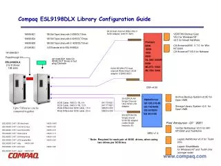
Chassis LPU Optical module Software and license Cluster cable Installation auxiliaries Others S12700 Configuration S12708 S12712
Chassis LPU Optical module Software and license Cluster cable Installation auxiliaries Others Chassis UniSTAReCFG • Basic configuration • Chassis • Installation suite • MPU • MPUA • SFU • SFUA, SFUC, SFUD • CMU • CMU • Power supply UniSTAR SCT When a product is added to UniSTAR SCT, the chassis type is determined. You can select one from multiple options.
Chassis LPU Optical module Software and license Cluster cable Installation auxiliaries Others Integrated Chassis Configuration Tips • The integrated chassis can be installed in a 19-inch cabinet or not installed in a cabinet. • The power module is located in bottom of the debugging integrated equipment. It is the mandatory component of the S12700 chassis. • All components support redundancy and hot-swapping. • AC and DC power supplies are supported, but only the power supplies of the same type can be installed on the same device. The AC and DC power supplies cannot be installed on a device. PoE is not supported. S12708 S12712
Chassis LPU Optical module Software and license Cluster cable Installation auxiliaries Others New MPU: MPUA MPUAOverview • MPUs of S12700 series are interchangeable • Function overview • CSS Combo port supports long-distance CSS through control plane. • Hardware OAM/BFD • Layered traffic shaping • USB-based deployment during which indicators show system status USBport Management port Clock port Cluster Comboport Comboport: Mini USB or RJ45 CSS Master indicator: If the indicator is on, the card is active; if the indicator is off, the card is standby. CSS ID: Eight indicators. If the indicator is on, it indicates the chassis ID in CSS. • Configuration tips: The dual control boards in 1+1 hot standby mode are recommended to improve system reliability.
Chassis LPU Optical module Software and license Cluster cable Installation auxiliaries Others New SFU SFUA SFU Overview • Universal SFU of S12700 series • Card overview • Three types, SFUA, SFUC, and SFUD are provided. When cards are fully configured, each slot delivers 160-640 Gbps bandwidth, which can reach 1.28 Tbps. • The SFUs are selected according to switching bandwidth. SFUs are not interchangeable. • The CSS bandwidth is 640 Gbps, which can be upgraded to 1.92 Tbps. OFLbutton CSS card slot SFUD • Note: When SFUA cards are fully configured on an S12708, a golden bandwidth of 480 Gbps is delivered. ★ • Note: S12712 does not support SFUC. ★ • Design highlights • OFL button: Press the OFL button to switch traffic to the other SFUs to ensure uninterrupted traffic forwarding. • Dual control channels: The system automatically detects faults and performs failover. • Configuration tips: • S12708 supports SFUA, SFUC, and SFUD. S12712 supports SFUA and SFUD. The SFUs of different types cannot be installed on the same chassis. • Each chassis can have at least one SFU and at most four SFUs installed. CSS card slot OFLbutton
Chassis LPU Optical module Software and license Cluster cable Installation auxiliaries Others Independent CMU Provides Uniform and Dynamic Monitoring CMU Four Major Functions Intelligent diagnosis and location • Detects voltage and temperature of LPUs • Detects faults in LPU clock Assets management • Manages component status • Manages component types • Records power-on time of LPUs • Monitors service plane environment changes independently Independent service monitoring Dynamic power control • Controls power of LPUs • Controls fan speed based on areas, to reduce noise and power consumption • Configuration tips: The chassis contains a CMU. A redundant CMU can be selected to improve system reliability.
Chassis LPU Optical module Software and license Cluster cable Installation auxiliaries Others Power Supply S12700 supports 2200 W AC and DC power supplies. The power supplies can be configured in N+M mode. Each of S12708 and S12712 supports six power supplies. The S12700 chassis does not support PoE. The following table describes the power supply specifications of S12700. • Configuration tips: • S12708/S12712 has the SFUA configured. The total number of LPUs and SFUAs should be greater than or equivalent to 2 and smaller than or equivalent to 16. It is recommended to configure two power supplies. • S12708/S12712 has the SFUC/SFUD configured. The total number of LPUs and SFUCs should be greater than or equivalent to 2 and smaller than or equivalent to 8. It is recommended to configure two power supplies. The total number of LPUs and SFUDs should be greater than or equivalent to 8 and smaller than or equivalent to 16. It is recommended to configure three power supplies. • To obtain detailed power consumption data, use the S12700 Power Consumption Calculator. The calculated power consumption includes the power consumption of optical modules.
Chassis LPU Optical module Software and license Cluster cable Installation auxiliaries Others S12700 Configuration S12708 S12712
Chassis LPU Optical module Software and license Cluster cable Installation auxiliaries Others S12700 LPU LPUs are selected based on interface types, MAC addresses, whether MPLS and unicast are supported, multicast routing table size, and whether cluster is supported. The service cards are installed in the LPU slots, and can be used by both models of S12700. A maximum of 12 LPUs can be configured for S12712 and 8 LPUs can be configured for S12708. You can select LPUs according to your service requirements and LPUs' features. Enter the number of required LPUs in the list.
Chassis LPU Optical module Software and license Cluster cable Installation auxiliaries Others S12700 Special LPUs S12700 provides multiple special LPUs for your selection.
Chassis LPU Optical module Software and license Cluster cable Installation auxiliaries Others S12700 Configuration S12708 S12712
Chassis LPU Optical module Software and license Cluster cable Installation auxiliaries Others Optical Module Precautions • The optical modules on two ends must have three identical parameters: • Transmission distance • Mode: single or dual • Center wavelength • Interpretability: SFP+ XFP • All FE and GE optical cards are hot swappable. • When a cluster is set up through fibers, the QSFP+ modules need to be configured. • BIDI: wavelengths on two ends match • TX1490/ RX1310 TX1310/ RX1490 • CWDM optical module • Connects switches to WDM • Supports all 10G XFP LPUs, but does not support SFP+ LPU • *BIDI –single-core bidirectional
Chassis LPU Optical module Software and license Cluster cable Installation auxiliaries Others S12700 Optical Module Use Precautions Pay attention to three specifications when selecting optical modules: transmission distance, connection attributes (such as single-mode/multimode of fibers and optical modules), and center wavelength. When two devices are connected, ensure that interfaces on both devices have the same indexes, such as the transmission distance, interconnection attributes, and center wavelength. Most single-mode optical modules configured for the S12700 support the "wide range receiving" feature. That is, optical signals, with the center wavelength of either 1310 nm or 1550 nm, can be received normally, but some optical modules can work normally only within a narrow range of center wavelength. Therefore, it is recommended that the center wavelengths of the optical modules on both devices be the same. When the S12700 is connected to a non-Huawei device, note that the optical modules of non-Huawei device may not support the "wide range receiving" feature. If the transmission distances of the optical modules on the connected devices differ greatly, the receiver of the optical module with the shorter transmission distance may be overloaded. This affects signal transmission reliability. Avoid this situation. If this situation cannot be avoided, configure an optical attenuator on the receiver with the shorter transmission distance. In addition, it is recommended to design for optical transmission during the networking to ensure reliable interoperation between devices. The optical interface boards of S12700 support hot swappable CWDM optical modules. CWDM optical modules must use the same wavelengths; otherwise, they cannot communicate with each other. When the switch is connected to WDM, the CWDM optical modules need to be used. The wavelengths and quantity of optical modules depend on the contract. To connect Ethernet devices, common optical modules are preferred. The single-fiber bidirectional optical modules must be used in pairs. Tx indicates the transmit wavelength and Rx indicates the receive wavelength. An optical module has the following wavelengths: Optical Transceiver-SFP-Tx1310/Rx1490-1.25Gb/s--3dBm--9dBm--19.5dBm-LC-Single-mode-10km Optical Transceiver-SFP-Tx1490/Rx1310-1.25Gb/s--3dBm--9dBm--19.5dBm-LC-Single-mode-10km
Chassis LPU Optical module Software and license Cluster cable Installation auxiliaries Others S12700 Configuration S12708 S12712
Chassis LPU Optical module Software and license Cluster cable Installation auxiliaries Others Software and LicenseConfiguration
Chassis LPU Optical module Software and license Cluster cable Installation auxiliaries Others S12700 Configuration S12708 S12712
Chassis LPU Optical module Software and license Cluster cable Installation auxiliaries Others Cluster Cable: The Only Hardware-based CSS2 in Industry S12700 switches form a cluster through CSS2 technique. Two switches are logically connected to form a large-capacity switch. Currently, cluster is implemented through the cluster subcards. Control channel Cluster cable Hardware cluster at the switching plane Hardware cluster at dual planes Hardware cluster at the control plane Power bus Power bus Power bus Power bus = Control channel Cluster cable MPU in standby chassis MPU in standby chassis MPU in active chassis MPU in active chassis MPU in active chassis MPU in standby chassis + CMU CMU CMU CMU SFU SFU SFU SFU LPU LPU LPU LPU SFU SFU SFU SFU LPU LPU LPU LPU • High reliability: Industry-leading switch fabric hardware clustering technology. Control packets and data packets of a cluster only need to be forwarded once by the SFUs. Control packets can be transmitted through specialized hardware channels. When the control link is faulty, services can be switched from the control plane to the forwarding plane. The dual-plane hardware clustering is more reliable. • Easy-to-use: Any interface on one chassis in the forwarding plane can establish a cluster with interfaces on any cluster card of the other chassis, and any interface on one chassis in the control plane can establish a cluster with interfaces on the other chassis, without occupying service slots. • Innovation: 1+N backup of control boards, implementing single-MPU cluster • Low-delay, high-bandwidth: reduces inter-chassis forwarding latency to 21 us, which is 58% lower than industry average. Cluster bandwidth can reach 1.92 Tbps. ★CSS2: Cluster Switch System Generation2
Chassis LPU Optical module Software and license Cluster cable Installation auxiliaries Others Cluster Cable Configuration CSS2 forwarding model When VS08 is installed on the SFU of S12712/S12708 as a cluster subcard (the cables of cluster subcards need to be configured independently), a maximum of four cluster subcards can be configured. The cluster subcard is installed on SFU. A cluster subcard provides eight SFP+ interfaces. CSS2 configuration scheme: Cluster subcards: 1-4 Cable cluster: A maximum of 32 SFP+ cables can be included. There are three cable lengths for selection: 1m, 3m, and 10m. Fiber cluster: The SFP+ optical modules can be used. A maximum of 80 km distance is supported. For short-distance transmission, the low-cost SFP+ AOC module which is equipped with fibers can be used. The transmission distance of this module is 10m. Data packets Cluster cable SFU SFU LPU LPU LPU LPU Chassis 1 Chassis 2 The CSS2 can be implemented using cables or fibers. SFP+ cables, SFP+ optical modules, and AOC cables are supported.
Chassis LPU Optical module Software and license Cluster cable Installation auxiliaries Others Cluster Cable Configuration Precautions CSS2 Connection Rule • Assume that 8 ports on a cluster subcard belong to a group. The cluster subcards are connected according to the following rules: • The 8 ports on one cluster subcard must be connected to the 8 ports on another subcard. It is recommended to connect the ports with the same port number together. • When a cluster has only one cluster subcard, at least one SFP+ port can be used.
Chassis LPU Optical module Software and license Cluster cable Installation auxiliaries Others S12700 Configuration S12708 S12712
Chassis LPU Optical module Software and license Cluster cable Installation auxiliaries Others Installation Auxiliaries Configuration Select fibers Select cables Select network cables Each network cable has two RJ45 connectors configured (part number: 14080082). You can select cable length according to customer requirements. The length of network cables is determined according to user requirements. The price increases for every 1 m increase in length (part number 25050014). • External cables used for assemble chassis (desk installation) • a. No cabinet is used. The assembly chassis obtains power from customer's PDF. • External cables used for assemble cabinet (with a power distribution box) • b. The cabinet and power distribution box obtain power from the customer's PDF, and provide power to the power modules. To configure fibers for a non-BIDI optical module, configure a Tx optical fiber and an Rx optical fiber of the same type for each optical interface. To configure fibers for a BIDI optical module, configure only one optical fiber. If single-mode optical modules are used, configure single-mode fibers. If multimode optical modules are used, configure multimode fibers. You can select fibers of different lengths. Huawei provides fibers of 10 m, 20 m, and 30 m.
Chassis LPU Optical module Software and license Cluster cable Installation auxiliaries Others Cable Configuration • Note: • The price of cables is included in the quotation of DC power module. By default, Huawei provides blue (-48 V) and black (GND) cables. If the customer needs other cables, the requirement should be added to the contract, and the cables may be purchased locally or from Huawei headquarters. • If the customer has not chosen cabinet and power distribution box, Huawei delivers a 3 m AC power cable for the AC power module. The power cable model is selected by Huawei according to standards in the corresponding country.
Chassis LPU Optical module Software and license Cluster cable Installation auxiliaries Others S12700 Configuration S12708 S12712
Chassis LPU Optical module Software and license Cluster cable Installation auxiliaries Others Cabinet: N66E Precautions • Standard 19-inchcabinetN66E • D*W*H: 600 x 600 x 2200 mm • Two enhanced cabinets: DC enhanced cabinet and AC enhanced cabinet • DC cabinetprovides 8-channel 60 A output. Each channel provides 2200 W output. The power distribution box provides 8-input-8-output or 4-input-8-output. • AC cabinet provides 4-channel 16 A output. Each channel provides 2500 W output. By default, the power distribution box provides 2-input-4-output. • The cabinet has a power distribution box equipped. Each channel of the power distribution box serves a power supply. If the number of power supplies is larger than the channels of a power distribution box, more power distribution boxes need to be configured. • When the N68Ecabinet (applicable to NE40E) is used, the power distribution box and external cables need to be configured. • Installed on concrete floor or ESD floor. • When the cabinet is installed on the ESD floor, the installation suite is required. S12712 one chassis in one cabinet S12708 one chassis in one cabinet ESD floorinstallation suite
Chassis LPU Optical module Software and license Cluster cable Installation auxiliaries Others Power Distribution Box 1. 2200W DC power distribution box • The power distribution box is an important part of a cabinet. It implements centralized power management, and is a mandatory component of the assembly cabinet. The 2200 W DC power distribution box provides 8-channel DC inputs (4-channel DC inputs can be implemented by adding copper fitting. The maximum input current should reach 120 A.). The 8-channel circuit breakers control 8-channel power outputs (each circuit breaker controls 1-channel output). The air breaker current is 63 A.
Chassis LPU Optical module Software and license Cluster cable Installation auxiliaries Others Power Distribution Box 2. 2200W AC power distribution box • The power distribution box is an important part of a cabinet. It implements centralized power management, and is a mandatory component of the assembly cabinet. The 2200 W AC power distribution box provides 2-channel AC inputs (4-channel AC inputs can be implemented by removing copper fitting). The 4-channel circuit breakers control 4-channel power outputs (each circuit breaker controls 1-channel output). The air breaker current is 16 A.
S12700Configuration S9700Configuration S7700Configuration Contents
Chassis LPU Optical module Software and license Installation auxiliaries S7700 S9700 Configuration S9703 S9706 S9712
Chassis LPU Optical module Software and license Cluster cable Installation auxiliaries Others Chassis • Basic configuration • Cabinet • Chassis • Installation suite • MPU • SRU/MCU • CMU • CMU • Power supply UniSTAReCFG UniSTAR SCT When a product is added to UniSTAR SCT, the chassis type is determined. You can select one from multiple options.
Chassis LPU Optical module Software and license Cluster cable Installation auxiliaries Others Cabinet: N66E Precautions S9712 one chassis in one cabinet S9706 two chassis in one cabinet • Standard 19-inch rack N66E • D*W*H: 600x600x2200 mm • No recommended configuration for S9703. A maximum of four S9703 chassis can be installed in a cabinet. • When the number of quoted 800 W AC power modules exceeds 8, one more power distribution box needs to be configured. • Three models are available: one standard and two enhanced. They differ in power. The models can be selected.. • When the N68E cabinet (applicable to NE40E) is used, the power distribution box and external cables need to be quoted for power distribution. • The cabinet can be installed on the concrete floor or ESD floor. • * When the cabinet is installed on the ESD floor, the installation suite is required. ESD floorinstallation suite
Chassis LPU Optical module Software and license Cluster cable Installation auxiliaries Others Integrated Chassis Configuration tips • The integrated chassis can be installed in a 19-inch cabinet or not installed in a cabinet. • All components support redundancy and hot-swapping. • AC and DC power supplies are supported, but only the power supplies of the same type can be installed on the same device. The AC and DC power supplies cannot be installed on a device. PoE is not supported.
Chassis LPU Optical module Software and license Cluster cable Installation auxiliaries Others Power Supply Calculate the quantity of required power supplies according to total card power consumption
Chassis LPU Optical module Software and license Cluster cable Installation auxiliaries Others MPU: SRUC/SRUD/MCU S9706/S9712 MPU-SRUD/SRUC S9703MPU-MCU • Hardware-based EOAM/BFDengine • Max power consumption 180 W • Integrated SFU Clock synchronization port (2) -SRUD Ethernet port Consoleport • Max power consumption 132 W • Integrated SFU • No SFU • Integrated monitoring module • Max power consumption 26 W Ethernet port Clock synchronization port (2) MON RS485 Consoleport Ethernet port USBport BITS port (2) Subcard slot -SRUC Consoleport Configuration tips • Recommended configuration: MPUs in 1+1 mode • The chassis includes a clock subcard (installed on the MPU)
Chassis LPU Optical module Software and license Cluster cable Installation auxiliaries Others CMU – Center Manage Unit CSS configuration tips CMU configuration tips SRUC is available in V2R3 2013Q2 • Only applicable to dual-MPU mode • 3 stack scenarios: • 2 S9706 • 2 S9712 • 1 S9706 vs 1 S9712 • A cluster consisting of two chassis, stack cable required: • 4 CSS cards * 2 = 8 cables • S9703 MCUA with a CMU integrated • S9706 /12 with one CMU configured • One more CMU can be configured to implement 1+1 backup • Suggestion: not needed • CMU faults do not affect service + SRUC CSS CMU functions: Manages power supplies and fans to implement intelligent energy-saving and reduce noise. CMU
Chassis LPU Optical module Software and license Installation auxiliaries S7700 S9700 Configuration S9703 S9706 S9712
Chassis LPU Optical module Software and license Cluster cable Installation auxiliaries Others LPU- S/F/E/B
Special LPUs S9700 provides multiple special LPUs for your selection.
Chassis LPU Optical module Software and license Cluster cable Installation auxiliaries Others Cluster V2R2 and later versions SRUC is available in V2R3 (2013Q2) SFU cluster: supported by S9706 /12 Service port cluster: supported by S9706 /12 Fibers between cities Intra-rack/inter-rack/inter-site Intra-rack Site 1 S7700 80km per hop SFU SFU S5700 S9700 S9700 S7700 Site 2 City A City B S5700 LPU LPU LPU LPU … … Chassis 1 Chassis 2 Configuration tips: Configuration tips: • CSS bandwidth: 320 Gbit/s non-blocking cluster bandwidth • Upgraded to 640 Gbit/s • Only supported by V2R3 SRUC • Cluster bandwidth: 1280Gbit/s, load balancing supported • LPUs on the two chassis: • 1:1 or 2:2; 2:1 not supported • Identical port rates • Stack cable or fiber Cluster/stack cable Not supported by S9703/S7703 clusters Packets
Chassis LPU Optical module Software and license Cluster cable Installation auxiliaries Others Service Port Cluster: LPU + Stack Cable • V200R002 and later versions support service port cluster. A cluster can be set up through cables or fibers. Service port clustering has the following constraints: • A service port cluster can be set up using only one LPU in the local chassis (one LPU in the peer chassis) or two LPUs in the local chassis (two LPUs in the peer chassis). However, two cluster cards cannot be connected to the same cluster card. • The 10G service port cluster can be set up through 1m passive SFP+ cables, 3m passive SFP+ cables (not supported by X12S), 10m active SFP+ cables, and SFP+ optical modules plus fibers. • The 40G service port cluster can be set up through 1m passive QSFP+ cables, 3m passive QSFP+ cables, 5m passive QSFP+ cables, and QSFP+ optical modules plus fibers. • The S9706/S9712 supports service port clustering. Only ports working at the same rate can be configured as cluster ports. The following table lists the cards supporting service port clustering. • The 10GE and 40GE ports on the S9700 can be used to set up cluster. You can select SFP+ optical modules and matching fibers to set up clusters through service ports. Alternatively, you can select the following cluster cables.
Chassis LPU Optical module Software and license Cluster cable Installation auxiliaries Others SFU Cluster: Cables for CSS Cards – S77/S97 • The CSS card is installed on the SRUCs of S9712/S9706, and is optional (The cluster cables are not delivered with cluster cards, and need to be configured independently.) • The CSS cards need to be configured in pairs. When the cluster cards are configured (cluster cables are not delivered with cluster cards), the cluster can be set up through SFP+ cables, SFP+ optical modules, or AOC cables. The cluster connection scheme is as follows: • Cable: 16 high-speed SFP+ cables, 1m, 3m, and 10m • Fiber: used together with SFP+ optical modules • Cluster connection rule is shown in the following figure: • On a cluster card, ports 1-4 belong to group 1 and ports 5-8 belong to group 2. The connections between cluster cards must meet the following requirements: • Ports in group 1 on one card must connect to ports in group 1 on another card. This rule also applies to ports in group 2. • A port in group 1 on one card can connect to any port in group 1 on another card. This rule also applies to ports in group 2. • Ports in group 1 and group 2 on one card must connect to different cards.
Chassis LPU Optical module Software and license Installation auxiliaries S7700 S9700 Configuration SFP+ SFP/eSFP XFP 10GE CWDM DWDM QSFP+
Chassis LPU Optical module Software and license Cluster cable Installation auxiliaries Others Optical Module Overview Precautions • The optical modules on two ends must have three identical parameters: • Transmission distance • Mode: single or dual • Center wavelength • Interpretability: SFP+ XFP • BIDI: wavelengths on two ends match • TX1490/ RX1310 TX1310/ RX1490 • CWDM optical module • Connects switches to WDM • Supports all 10G XFP LPUs, but does not support SFP+ LPU • *BIDI –single-core bidirectional Fiber configuration