Fusion Design Overview
Understand the role of Design in implementing system behavior specified in Analysis, with a focus on object interactions and messaging structures. Learn how to create, record, and check Object Interaction Graphs for accurate system operation representation. Gain in-depth insights into creating Class Descriptions, Data Dictionary, and Inheritance Graphs. Master terminology such as Controllers, Collaborators, and Visibility Graphs for effective software design. Explore the importance of identifying objects, establishing roles, deciding on messages, and ensuring consistency with the System Specification.

Fusion Design Overview
E N D
Presentation Transcript
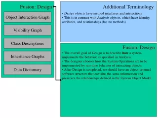
Fusion Design Overview • Design objects have method interfaces and interactions • This is in contrast with Analysis objects, which have identity, attributes, and relationships (but no methods) Fusion: Design Additional Terminology Object Interaction Graph Visibility Graph Class Descriptions • The overall goal of Design is to describe how a system implements the behavior as specified in Analysis • The designer chooses how the System Operations are to be implemented by run-time behavior of interacting objects • After Design is completed, we should have an object-oriented software structure that contains the same information and preserves the relationships defined in the System Object Model. Fusion: Design Inheritance Graphs Data Dictionary
Object Interaction Graph • Controllers receive and handle system operations (perhaps by dispatching messages to other objects) • Collaborators are other objects (that are not controllers) that help complete the system operation Fusion: Design Additional Terminology Object Interaction Graph Visibility Graph Class Descriptions • The Object Interaction Graph will provide what methods are needed for each class. • The Object Interaction Graph details the behavior of each system operation by building the object messaging structures that will satisfy the functionality as specified in the operation schema. • In other words, for each operation schema, we want to show the actual interactions between objects. • The process suggested is (Coleman 1994, p69): • Identify relevant objects • Establish the role of each object • Decide on messages between objects • Record these interactions in an object interaction graph Object Interaction Graph Inheritance Graphs Data Dictionary
Object Interaction Graph Notation (From Coleman 1994, p259)
Object Interaction Graph Notes A dashed box denotes a Collection of objects, typically a list or array. A solid box denotes a Design Object An arrow represents message passing from a client to a server, typically a function or method call. The number in parenthesis represents ordering of messages. Message (1.1) must complete in order for message (1) to complete. (From Coleman 1994, p259)
Creating Object Interaction Graphs Creating Object Interaction Graphs • For each Operation Schema / System Operation, do the following: • 1. Identify relevant objects involved in the implementation of the system operation. • The Reads clause provides a list of the objects that a system operation accesses but doesn't modify. • The Changes clause lists the objects changed by the functional behavior. • Other objects may be involved in addition to those explicitly listed in the schema. For example, other objects may be introduced for abstraction purposes and not identified on the analysis models. • The Sends clause of the schema lists output events to agents of the system. The actual object that does this may need to be created.
Creating Object Interaction Graphs Creating Object Interaction Graphs • 2. Establish the role of each object. • Identify the controller (i.e. object receiving system operation) • Identify the collaborators involved (i.e. object not a controller) • 3. Decide on the messages between objects. • Each object provides different pieces of functionality. • Functionality is composed by message passing between objects. • 4. Record interaction of identified objects on Object Interaction Graph. • Each object provides part of the functionality of the operation • This info can be used to define the object method interface. • Add a text description of each method in the data dictionary, explaining what the method does and the algorithm used to solve the system operation.
Checking Object Interaction Graphs Checking Object Interaction Graphs • 1. Consistency with System Specification • Ensure that each of the classes in the System Object Model is represented in at least one Object Interaction Graph • 2. Verification of Functional Effect • Ensure that each Object Interaction Graph implements the System Operation correctly by checking the Results clause.
Visibility Graph • Referencing is the process of identifying and addressing objects. • A Client is any object requesting the services of another object, called a Server. Fusion: Design Additional Terminology Object Interaction Graph Visibility Graph Class Descriptions • The Visibility Graph will provide object attributes for each class description. • Visibility Graphs define the communication paths between objects • For each class, identify what object references are needed, and what kind of reference it is. • A reference can have four different attributes: • Lifetime (dynamic / permanent) • Sharing (shared / exclusive) • Binding (bound / unbound) • Mutability (constant / variable) • In other words, for each class, identify the objects each instance of that class will need to reference, and the kind of reference to those objects (see Coleman 1994, p83-84). • Use the Object Interaction Graphs to create the Visibility Graph Visibility Graph Inheritance Graphs Data Dictionary
Visibility Graph Notation Visibility Graph Notation (From Coleman 1994, p260)
Visibility Graph Notes Visibility Graph Notes A reference is constant if it cannot be changed after initialization. Denote this by placing the keyword constant next to the server name (even though it’s really the reference that is constant, not the server - JH). Server Lifetime Bound means that this server will be deleted when its client is deleted. In this case, put the server box inside the client box. Exclusive reference means that there is at most one instance of a client using this server at a given time. Use a double box to denote this, a single box if the server can be shared. A Permanent reference means that we can always access this object. Use a solid line to denote this. A Dynamic Reference is typically implemented by a parameter or local variable. Use a dashed line to denote this. (From Coleman 1994, p260)
Creating Visibility Graphs Creating Visibility Graphs • For each Object Interaction Graph, do the following: • 1. Inspect each Object Interaction Graph • Each arrow going from a client to a server requires a visibility reference to the server • 2. Annotate the arrow with visibility information, detailing: • Reference lifetime (dynamic / permanent) • Server visibility (shared / exclusive) • Server binding (bound / unbound) • Reference mutability (constant / variable) • 3. Construct the Visibility Graph • For each class, find all instances where it is a client • Use all of the annotated arrows
Checking Visibility Graphs Checking Visibility Graphs • 1. Consistency with Analysis • Relationships identified in Analysis define invariants • Ensure that the structures defined in the visibility graphs maintain the relationships between classes. • For each relationship in the System Object Model, ensure that there is a path of visibility between the corresponding classes. • 2. Mutual Consistency • Ensure that exclusive server objects are not referenced by more than one instance of a client • 3. Completeness • Ensure that all message passing defined in the Object Interaction Graphs are realized in the Visibility Graphs.
Class Descriptions • Fusion makes a distinction between a Data Attribute and an Object Attribute. Essentially, an Object Attribute is a reference to an object. A Data Attribute is any other kind of attribute (e.g., String, int, char, etc). Fusion: Design Additional Terminology Object Interaction Graph Visibility Graph Class Descriptions • Class Descriptions are the specifications from which coding begins. It is the final step in the design phase. • We take information from the object model, the object inheritance graphs, and the visibility graphs. • Methods for each class are derived from the object interaction graphs. • Data Attributes for each class are derived from the system object model and the data dictionary. Additional attributes may be derived from method descriptions. • Object Attributes for each class are derived from the visibility graph for that class. Class Descriptions Inheritance Graphs Data Dictionary
Inheritance Graphs Fusion: Design Additional Terminology Object Interaction Graph Visibility Graph Class Descriptions • Inheritance Graphs are used to refactor the inheritance from Analysis to capture common patterns in the objects, including: • Common methods • Common interaction patterns • Common visibility structures • Use the System Object Model, the Object Interaction Graphs, and the Visibility Graphs to construct the Inheritance Graphs. Inheritance Graphs Inheritance Graphs Data Dictionary
Overview of Creating Class Definitions Object Interaction Graph Methods System Object Model Classes and Data Attributes Data Dictionary Visibility Graph Object Attributes Inheritance Graphs Inheritance Information 1 2 3 4 Class Descriptions
Checking Design Models Fusion: Design Additional Terminology Object Interaction Graph Visibility Graph Class Descriptions • For each analysis relationship, there is a visibility reference between the corresponding classes. • Exclusive server objects are truly exclusive. • Visibility graphs cover all needed interactions. • Review data attributes by checking that all data attributes from the system object model are recorded. • Review object attributes by checking that all visibility references are recorded. • Review methods and parameters by checking that all methods from object interaction graphs are recorded. • Ensure that the Inheritance Graph retains the sub-type relations from Analysis. Checking Design Models Inheritance Graphs Data Dictionary