Download
1 / 13
200 likes | 619 Vues
Chapter 5 Jones Calculus and Its Application to Birefringent Optical Systems. Lecture 1 Wave plates. Wave plates ( retardation plates ) are optical elements used to transform the polarization states of light. They are made from one or more pieces of birefringent crystals.

E N D
Chapter 5 Jones Calculus and Its Application to Birefringent Optical Systems Lecture 1 Wave plates Wave plates(retardation plates) are optical elements used to transform the polarization states of light. They are made from one or more pieces of birefringent crystals. • Let us consider a plate made of a uniaxial crystal with a thickness of l. Usually the plate is cut so that its optic axis lies in the plane of the plate surface. • For a normally incident light, the polarization directions of the two eigenwaves both lie in the surface of the plate, and are mutually orthogonal. One polarization direction coincides with the optic axis, with a refractive index ne. The other is perpendicular to the optic axis, with a refractive index no. • The polarization direction with the larger refractive index is called the slow axis, and the polarization direction with the smaller refractive index is called the fast axis, regardless of whether it is an ordinary light or an extraordinary light. The refractive indices are then designated as nf and ns, respectively.
In the frame of the slow and fast axes, suppose the input light is linearly polarized with the field The phase difference (retardationor retardance) between the f and s polarization is then f f s s f l s
Half-wave plates and quarter-wave plates 1) A half-wave plateconverts a linearly polarized light into another linearly polarized light, mirrored by the fast or slow axis. 2) A quarter-wave plateconverts a linearly polarized light into a circularly polarized light, when the input polarization is 45° to the fast and slow axes. At other azimuth angles it converts a linearly polarized light into an elliptically polarized light oriented along the fast or slow axes. f f s s f f f f f f s s s s s s Half-wave plate Quarter-wave plate Quarter-wave plate Quarter-wave plate
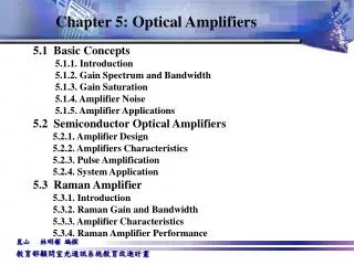
Zero-order and multiple-order wave plates A half-wave plate with a retardation of is called a zero-order half-wave plate. The thickness of the plate is This thickness is apparently not easy to fabricate and not easy to handle. We can use a thickness of which is a multiple-order wave plate. The wavelength sensitivity of a half-wave plate is Therefore a multiple-order wave plate has a limited bandwidth. One technique to solve this problem is to make a compound zero-order wave plate from two plates, with their optic axes intercrossed. The difference in thickness between the two plates determines the overall retardation. Zero-order wave plates thus have broad bandwidths.
y (e) y (o) MgF2 x (o) x (e) Crystal Quartz Reading: Achromatic wave plates: Estimation of l1 and l2 (e.g., QWP): In the wavelength range considered, the phase retardation should be as close as possible top/2(minimum rms, or similar criteria). l1=603mm, l2=477mm. Question: Why do we need two materials? For a normal compound zero-order wave plate (one material), l1-l2 is fixed, thus is fixed. For achromatic wave plates (two materials), l1 and l2 can be chosen to minimize , which greatly expands the bandwidth.
Lecture 2 Jones matrix 5.1 Jones matrix formulation While it is not difficult to track the polarization of light passing through an individual wave plate or polarizer using junior algebra, when there is a combination of several such optical elements, and a certain goal is aimed, the algebra involved can be complicated. Jones calculus is created to study the transformation of polarization using linear algebra, where the polarization of light is represented by a Jones vector, and the function of an optical element is represented by a 2×2 matrix. A fixed lab coordinate system (instead of the principle axes of the crystal) is normally used. The azimuth angleof the retardation plate is defined as the angle between the slow axis and the lab x axis, or between the fast axis and the lab y axis. The light is propagating in the –z direction.
Wave plates: The polarization state after the plate, in the s-f coordinates, is then Here is the phase retardation, and is the average phase change. is the Jones matrix for the wave plate expressed in its own principle s-f coordinate system. In the x-y coordinate system the polarization state after the plate is Let us first derive the 2×2 matrix for a wave plate. Suppose the input light has an arbitrary polarization state . At the surface of the plate this light need to be decomposed into the two eigenwaves, which is a transformation to the s-f coordinate system.
The overall effect of the retardation plate is then The e-iffactor can be dropped if we are not dealing with interference. Therefore a retardation plate is characterized by its phase retardation G and azimuth angle y , and is represented in the lab frame by Note that the transformation is unitary: W+W=1. It does not change the inner product between two Jones vectors. This is because a wave plate does not absorb light. Linear polarizers (analyzers): An ideal linear polarizer with its transmission axis on the x axis is For a linear polarizer oriented at an azimuth angle y, the Jones matrix is Particularly
Combination of wave plates and polarizers: For a series of wave plates and polarizers, we need to just multiply the Jones matrix of individual element in sequence. Wave plates examples: Half-wave plate: A half-wave plate with its slow axis oriented at y =45°. The input light is linearly polarized in the vertical direction: For a general azimuth angle y, a half-wave plate will rotate a horizontally or vertically polarized light by 2y. A half-wave plate will change a left-handed circularly polarized light into a right-handed circularly polarized light, and vice versa, regardless of the azimuth angle of the plate.
Quarter-wave plate: A quarter wave plate with its slow axis oriented at y =45°. The input light is linearly polarized in the vertical direction: Our textbook is wrong here. If the input light is horizontally polarized, it will be changed into a right-handed circularly polarized light.
5.2 Intensity transmission For a Jones vector , the corresponding electric field is .The absolute intensity of the light is then For convenience, if we only care the relative intensity of light in one medium (e.g., air), the factor (1/2)ev is a constant and can be dropped. We therefore define the intensity of light as For a Jones matrix transformation , the intensity transmittance is then
Intensity transmission examples: A birefringent plate sandwiched between two parallel polarizers: Suppose the transmission axes of the polarizers are both vertical. The slow axis of the birefringent plate is oriented at 45° from the x axis. The plate introduces a phase retardation The Jones matrix is Let the incident light be unpolarized, with unit intensity. After the first polarizer, the Jones vector is The electric field of the final transmitted light is The intensity transmittance is
A birefringent plate sandwiched between two crossed polarizers: As above, but let the transmission axis of the final polarizer be horizontal. The electric field of the final transmitted light is The intensity transmittance is This is complementary to the case of parallel polarizers. In both cases the transmission is a sinusoidal function of wave number 1/l.