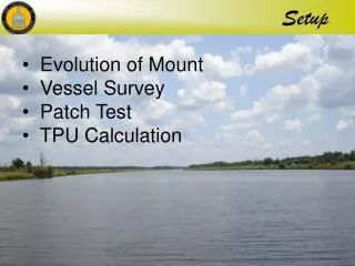
Setup
Setup. Evolution of Mount Vessel Survey Patch Test TPU Calculation. Evolution of Mounts. Side Mount. Side Mount Patch Test. There was also a flexing of the transducer mount. Original Bow Mount Design. Mock-Up Design. NA VO Bow Mount Design. Final Bow Mount.

Setup
E N D
Presentation Transcript
Setup • Evolution of Mount • Vessel Survey • Patch Test • TPU Calculation
Side Mount Patch Test There was also a flexing of the transducer mount
Final Bow Mount Aluminum Bow Mount
60° 4 m 13.86 m 79.25° 4 m 21.07 m 1.87 m Angled Mount Theoretical Comparison Normal Mount Angled Mount (35°) *** 79.25° = 0.5 m beam separation
79.25° 4 m 0.513 m 0.490 m 0.449 m 0.469 m Swath Calculations 120° swath with 480 beams = 0.25° per beam
4 m 21.07 m 1.87 m 1.9 m 16.8 m Post Survey Analysis Theoretical Swath 79.25° Actual Swath
Post Survey Analysis Note: Assumes full profile with traditional mount
The Pudding The Air-Land-Sea Interface!
The Pudding The 2005 Summer Survey Behold: a data gap… or two… dozen… As compared to 2008…
Bow Mount – Lessons Learned • Confirm Repeatability • Does it go back to the same place? • Support needed for transit • GPS PPK antenna location • Grass accumulation • Thicker walled aluminum pipe • Welds must be contiguous
Vessel Survey Determining the relative offsets of the IMU, Echosounder and Positioning Antenna…
BOLTS Vessel Survey • Phase 1 – Determine the positions of the bolts
Vessel Survey • Phase 1 – Determine the positions of the bolts Vertical positioning computed through digital level run… Horizontal positioning computed with total station…
Vessel Survey • Phase 1 – Determine the positions of the bolts Wolfmate™ provides an interface for feeding hundreds of total station observations into Adjust software…
Vessel Survey • Phase 1 – Determine the positions of the bolts • 89 Distance Obs. • 76 Angle Obs. • Only a 2D Solution Horizontal Misclosure ~ 3mm
Vessel Survey • Phase 2 – Position the IMU, Sounder & Antenna
} ∆≈2mm Vessel Survey • Phase 2 – Position the IMU, Sounder & Antenna
Reflectors Reference Azimuth of vessel Vessel Survey • Phase 2 – Position the IMU, Sounder & Antenna Antenna IMU Multibeam
PORT FWD Vessel Survey • Phase 3 – Align the Coordinate System
Vessel Survey • Lessons learned • Sticker placement must be horizontal • Adjust prism constant for stickers • Level vessel • Have IMU bolted to vessel (not glued) • Use digital level • Consider using both IR and red laser • Do not use GPS for positioning bolts (AB-PE3) • Consider adding more bolts (AB-PE4?)
Patch Test Target • Spare parts • Air-filled PVC • Quick & Easy • A lack of local targets
Patch Test Problem Central Beam Nadir Where do you place the Target?
Patch Test • Aim is to isolate and quantify misalignment errors • Placing the Target at Nadir on our mount is the equivalent of placing the Target in the outer swath of a traditional mount (Center Beam = Nadir) • Cross contamination of errors occur
Modified Patch Test Timing Run 1: Speed: Y Run 2: Speed: Y x 2 Roll Run 1: Speed: Y Run 2: Speed: Y (Same speed as Run 1, in a reciprocal direction)
Modified Patch Test Run 1: Speed: Y Run 2: Speed: Y Pitch Yaw Run 1: Speed: Y Run 2: Speed: Y (Same speed as Run 1, in a reciprocal direction)
2 second Timing Error With the application of PPK GPS a 1.98 second timing error is introduced The Cause remains unknown
TPU Calculations ? ? ? ? ? ? ? ? ? ? ? ? ? ? ? ? ? ? ? ?
TPU Calculations • Uncertainties to be estimated… • Gyro, Heave, Roll, Pitch, Speed • Navigational Positioning (PPK) • IMU/Antenna/Sounder Offsets • Loading, Draft & Delta-Draft • Tide • Timing & IMU/Sounder Alignment
TPU Calculations • Gyro, Roll, Pitch, Heave, Speed • Gyro/Roll/Pitch… 0.020 • Heave… 0.05m or 5% • Speed… 0.03 m/s
TPU Calculations • Navigational Positioning (PPK) … 0.05m
. 5mm ≈0 ≈3mm TPU Calculations … 0.005m • IMU/Antenna/Sounder Offsets • Determined through a combination of a network survey, vessel survey and a digital level run.
TPU Calculations • Delta-Draft • Four lines run in same direction at different speeds … 0.02m • Draft • Uncertainty in draft measurement – measured with a plumb bob while hanging from the side of the vessel… … 0.03m • Loading • Vertical changes in the vessel due to fuel consumption, crew member presence, etc… … 0.03m
TPU Calculations • Tide Values (measured and zoning) • Measured… • Zoning… 0.01m 0.05m
TPU Calculations • Timing & IMU/Sounder Alignment • (derived through patch test data) • Timing… 0.1 sec • Gyro Align… 0.30 • Pitch/Roll Align… 0.580