Interval Partitioning of a Flow Graph
120 likes | 277 Vues
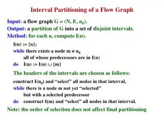
Interval Partitioning of a Flow Graph. Input: a flow graph G = (N, E, n 0 ). Output: a partition of G into a set of disjoint intervals. Method: for each n, compute I(n). I(n) := {n}; while there exists a node m n 0 all of whose predecessors are in I(n) do I(n) := I(n) {m}

Interval Partitioning of a Flow Graph
E N D
Presentation Transcript
Interval Partitioning of a Flow Graph Input: a flow graph G = (N, E, n0). Output: a partition of G into a set of disjoint intervals. Method:for each n, compute I(n). I(n) := {n}; while there exists a node m n0 all of whose predecessors are in I(n) do I(n) := I(n) {m} The headers of the intervals are chosen as follows: construct I(n0) and “select” all nodes in that interval, while there is a node m not yet “selected” but with a selected predecessor do construct I(m) and “select” all nodes in that interval. Note: the order of selection does not affect final partitioning
Note: node 2 dominates nodes 3, 4, 5. node 2 is the only entry of the interval (header). Initially: I(1) = {1} -1 is selected Pick node 2: I(2) := {2} then execute while loop I(2) := {2} U {3} U {4} U {5} 2, 3, 4, 5 are selected Note: After 1, the only node we can pick is 2, because it is the only one with selected predecessor! Interval Partitioning Example 1 Natural loop 2 3 4 5
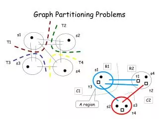
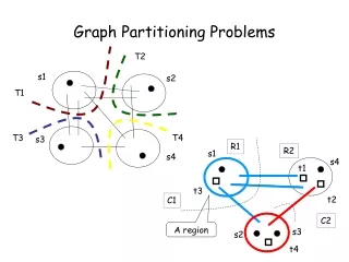
Interval Graphs From the intervals of one flow graph G one may construct a new flow graph I(G) by the following rules: • Nodes: The nodes of I(G) correspond to theintervals in the interval partition of G. • Initial node: The initial node of I(G) is the interval thatcontains the initial node of G. • Edges: There is an edge from interval I to interval J if and only if there is an edge from some node in I to the header of J. Note: There could not be an edge entering some node n of J other than the header, because there would be no way n could have added to J in interval partitioning algorithm.
1 1,2 2 3 3 1,2 4 1,2 4,5,6 3 5 6 1, ..., 10 7 4, …, 10 3, …, 10 7,8,9,10 8 9 10 Interval Graphs (Cont) Limit flow graph of G: Applying interval partitioning and interval graph construction in alternation, leads to a sequence of graphs G, I(G), I(I(G)) … In(G) where the nodes of In(G) are in one interval. In(G) is the limit. Property: A flow graph is reducible if and only if its limit flowgraph is a single node (historic definition).
T1-T2 Analysis Motivation: A convenient way to achieve same effect as interval analysis. Definition: Repeatedly apply two simple trans formations to flow graphs: - T1: If n is a node with a loop, i.e., an edge nn, delete that edge. - T2: If there is a node n n0 that has a unique predecessor, m, then m may consume n by deleting n and making all successors of n (including m, possibly) be successors of m. Facts: - By applying (T1 |T2 )k (G) until no further application is possible then a unique flow-graph results. - The flow graph (T1 |T2 )k (G) is the limit flow-graph of G.
Example of T1 -T2 Analysis T2 T1 T2 T2 a a a ab abcd b c b cd b cd cb d
Example of T1 -T2 Analysis Regions: a set of nodes N with a headerdominating all other nodes. Property: While reducing a flow graph with T1-T2 following holds all the time: T2 T1 T2 T2 a a a ab abcd b c b cd b cd cb d T2 T1 T2 T2 • A node represents a region of G. • An edge from a to b represents a set of edges of G. Each is from some node in a to header of b. • -Each node and edge of G is represented by exactly one node or edge of the current graph.
‘Optimizations’ of Basic Blocks Equivalent transformations: Two basic block are equivalent if they compute the same set of expressions. -Expressions: are the values of the live variables at the exit of the block. Two important classes of local transformations: -structure preserving transformations: • common sub expression elimination • dead code elimination • renaming of temporary variables • interchange of two independent adjacent statements. -algebraic transformations (countlessly many): • simplify expressions • replace expensive operations with cheaper ones.
The DAG Representation of Basic Blocks Directed acyclic graphs (DAGs) give a picture of how the value computed by each statement in the basic block is used in the subsequent statements of the block. Definition: a dag for a basic block is a directed acyclic graph with the following labels on nodes: • leaves are labeled with either variable names or constants. • they are unique identifiers • from operators we determine whether l- or r-value. • represent initial values of names. Subscript with 0. • interior nodes are labeled by an operator symbol. • Nodes are also (optionally) given a sequence of identifiers for labels. - interior node computed values - identifiers in the sequence – have that value.
t1:= 4*i t2:= a[t1] t3:= 4*i t4:= b[t3] t5:= t2 * t4 t6:= prod + t5 prod:= t6 t7:= i + 1 i:= t7 if i <= 20 goto 1 Three address codeCorresponding DAG Utility: Constructing a dag from 3AS is a good way of determining: common sub expressions (expressions computed more than once), which names areused inside the block but evaluated outside, which statements of the block could have their computed valueused outside the block. Example of DAG Representation t6, prod + t5 * prod t4 (1) t2 [] [] <= t1, t3 t7, i * + a b 20 4 i0 1
Constructing a DAG Input: a basic block. Statements: (i) x:= y op z (ii) x:= op y (iii) x:= y Output: a dagfor the basic block containing: - a label for each node. For leaves an identifier - constants are permitted. For interior nodes an operator symbol. - for each node a (possibly empty) list of attached identifiers - constants not permitted. Method: Initially assume there are no nodes, and node is undefined. • If node(y) is undefined: created a leaf labeled y, let node(y) be this node. In case(i) if node(z) is undefined create a leaf labeled z and that leaf be node(z). • In case(i) determine if there is a node labeled op whose left child is node(y) and right child is node(z).If not create such a node, let be n.case(ii), (iii) similar. • Delete x from the list attached to node(x). Append x to the list of identify for node n and set node(x) to n.