Download
1 / 40
400 likes | 508 Vues
N. Tsoupas. Characterization the W(Tungsten) stripping foil of Au +77 ions at g =10.5. What is the W stripping foil of the AtR Line? The stripping foil is made out of Tungsten material with dimensions 10[cm]x10[cm] and is 0.025 [mm] thick (48.3 m g/cm 2 ).

E N D
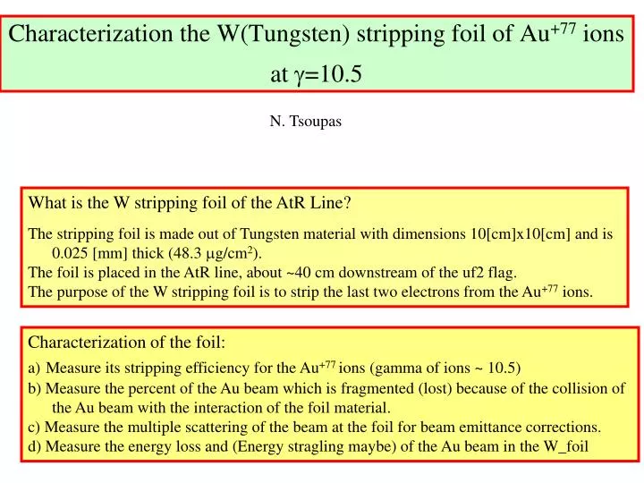
N. Tsoupas Characterization the W(Tungsten) stripping foil of Au+77 ions at g=10.5 What is the W stripping foil of the AtR Line? The stripping foil is made out of Tungsten material with dimensions 10[cm]x10[cm] and is 0.025 [mm] thick (48.3 mg/cm2). The foil is placed in the AtR line, about ~40 cm downstream of the uf2 flag. The purpose of the W stripping foil is to strip the last two electrons from the Au+77 ions. Characterization of the foil: a)Measure its stripping efficiency for the Au+77 ions (gamma of ions ~ 10.5) b) Measure the percent of the Au beam which is fragmented (lost) because of the collision of the Au beam with the interaction of the foil material. c) Measure the multiple scattering of the beam at the foil for beam emittance corrections. d) Measure the energy loss and (Energy stragling maybe) of the Au beam in the W_foil
MotivationWhy the need to “characterize” the W_stripping _foil? • The AGS provides ions of Au+77 at g=10.5 • For certain reasons we want to inject into RHIC fully stripped ions, like Au+79. • A stripping foil inserted in the AtR line strips the electrons from the Au+77 ions. • The stripping foil must be thick enough to provide a good fraction of Au+79 ions (Uf2 flag provides ~100% Au+79 ions) BUT thin enough to minimize: • The fragmentation of the Au ions. (Uf2 generates 4% beam loss) • The increase of the beam emittance. (de/e increase due to Uf2 ~15%) • The increase of the momentum spread (dEloss/E in Uf2 ~0.0025) • We want to determine the optimum thickness of the W_foil
Schematic arrangement of current transformers (xf)and Flags/stripping foils in the U/W line during Au+77 +79 transport 4.250 bend Au+77g=10.5 Au+77 +78 +79 80 bend uxf1 200 bend W foil 0.025 mm Uf2 1 mm Al2O3 Uf3 Wf1 Uf4 Uf5 Wf2 Wf3 uxf3 Au+77 +78 +79 wxf1 Au+77 +78 +79 Uf3,Uf4, Uf5 (2 mil Cd2O2S:Tb on 1 mil Al sub tray) Wf1,Wf2, Wf3 (1mm Al2O3) tray)
Theoretical background to calculate stripping efficiency x=e-s·T =>Survival probability of a single electron on the Ion after passing through a foil. T => Target thickness s=>One electron Ionization cross section (from Tables) Yn={N!/[n!(N-n)!]}·xn·(1-x)(N-n) {N=2, n=0,1,2} Yn = % of Charge State Population Y2 = x2 = e-2·s·T/(1.66·At) n=2 Au+77 => Au+77 No Ionization Y1=2· x · (1-x) = 2 ·e-s ·T/(1.66·At) ·(1-e-sT /(1.66·At)) n=1 Au+77 => Au+78 One electron Y0=(1-x)2 = (1-e-sT /(1.66·At) )2 n=0 Au+77 => Au+79 Two electron T=> Target thickness in mg/cm2 At=> Atomic Number of target material (At=184 Zt=74 for Tungsten) s=> Ionization Cross section in barns (Au+77 to Au+78,+79 s =3.9x10⁴ barns. see slide at end ) Target thickness (T) and/or Ionization cross section (s) can be calculated from the measurements proposed in this presentation.
Theoretical background to calculate the multiple scattering angle qrms=14.98·(Zp/p·b)·(T/X0)1/2{1.0+(1/9)·log10(T/X0)}[mrad] Zp => Atomic Number of projectile p => momentum of projectile in GeV/c T => Target thickness in mg/cm2 X0 => Interaction length in mg/cm2 b = v/c e'=e0·{1+b·(qrms)2/e0}1/2(qrmsto be calculated) e' = beam emittance after foil (from measurement) e0 = beam emittance before foil (from measurement) b = beta function at the foil. (from measurement)
Theoretical background to calculate the Energy Loss Weuse “SRIM” code. No Experimental data for reliable prediction . Our measurement will be a data point of Au+77 at (g=10.5) in W_foil
Predictions and two Measurements of some physical quantities when Au+77 ions pass through few targets. Note that the amount of Au+77 depends strongly on s and T
(A) Procedure to measure the stripping efficiency of the W_foil for Au+77 ( g=10.5). 1. With the stripping foil retracted, tune the U/W line for Au+77 beam transport. Measure: • a) The beam current at uxf1, uxf3 and wxf1. • b) Record the beam images (position,size) at the flags uf2, uf3, uf4, uf5, wf1, wf2, wf3. 2. Insert the W stripping foil. Measure, after tuning U/W line, separately, for Au+77, Au+78, and Au+79 : • a) The beam current at uxf1, uxf3 and wxf1. (Determine charge state population) • b) Record the beam images (position, size) at the flags uf2, uf3, uf4, uf5, wf1, wf2, wf3. (Determine multiple scattering and emittance growth) • In Task #2 the charge states of Au+77, Au+78, and Au+79 will be present downstream of the stripping foil. The xcod of the various charge states appears in the next slide. (The measured xcod may help determine the energy loss of ions in the foil) • See next 6 slides (8 to 13) for more details.
Procedure to measure the stripping efficiency of the W_foil for Au+77 ( g=10.5).
Procedure to measure the stripping efficiency of the W_foil for Au+77 ( g=10.5).
Procedure to measure the stripping efficiency of the W_foil for Au+77 ( g=10.5).
Procedure to measure the stripping efficiency of the W_foil for Au+77 ( g=10.5).
Procedure to measure the stripping efficiency of the W_foil for Au+77 ( g=10.5).
Predictions of the Xcod for the Au+77 Au+78 and Au+79 at the location of the flags. Au+77 Au+77 W_foil Au+78 Au+79
Procedure to measure the stripping efficiency of the W_foil for Au+77 ( g=10.5). • Theoretical predictions indicate that there are NO Au+77 ions. Also for U/W line tune for Au+77 transport the Au+78 and Au+79 charge states will “crash” on the beam line before they make it to the current transformers. • Tune the 8o and 20o bends of U/W lines for optimum transport of Au+77. Read the current transformers and observe any image on the flags. • Tune the 8o and 20o bends of U/W lines for optimum transport of Au+78. Record the reading of the current transformers and observe any beam image on the flags. • Tune the 8o and 20o bends of U/W lines for optimum transport of Au+79. Record the reading of the current transformers and observe any beam image on the flags.
(B): Procedure to measure the fragmentation of the Au ions ( g=10.5) by the W_stripping_foil. 1. With the stripping foil inserted, tune the U/W line for Au+79 beam transport. Measure: • a) The beam current at uxf1, uxf3 and wxf1. • b) Record the beam images (position,size) at the flags uf2, uf3, uf4, uf5, wf1, wf2, wf3. 2. With the stripping foil inserted, tune the U/W line for Au+78 beam transport. Measure: • a) The beam current at uxf1, uxf3 and wxf1. • b) Record the beam images (position,size) at the flags uf2, uf3, uf4, uf5, wf1, wf2, wf3. • Compare ratios of (uxf3/uxf1)|Au+77,+78, +79 and (wxf1/uxf1)|Au+77, +78, +79 of task1 # 1,2 of procedure (B) with the corresponding ratios (uxf3/uxf1)|Au+77 and (wxf1/uxf1)|Au+77 of task #1 of Procedure (A)
Measurements required to calculate the stripping efficiency of the W_foil and fragmentation of Au+77 ions.In Table below (?) designates, “to be measured”.
(B) Procedure to measure the multiple scattering of the beam Au+77 ( g=10.5) due to W stripping foil 1. With the stripping foil retracted, tune the U/W line for Au+77 beam transport. Measure: • a) The beam current at uxf1, uxf3 and wxf1. • b) Record the beam images (position,size) at the flags uf2, uf3, uf4, uf5, wf1, wf2, wf3. • Calculate beam emittance using measured beam profiles from uf3, uf4, and uf5. Also using wf1, wf2 and wf3. 2. Insert the W stripping foil and tune U/W line for Au+78. Measure: • a) The beam current at uxf1, uxf3 and wxf1. • b) Record the beam images (position,size) at the flags uf2, uf3, uf4, uf5, wf1, wf2, wf3. • Calculate beam emittance using beam measured profiles from uf3, uf4, and uf5. Also using wf1, wf2 and wf3. 2. Repeat task #2 with the U/W lines tune for Au+79
(C) Procedure to measure the energy loss of the beam Au+77( g=10.5) due to W stripping foil • The most straightforward way of measuring the Energy loss {DE(Au+77)} of the beam after it passes through the W_foil is to measure the {xcod(Au+77 W_foil) - xcod(Au+77 NO_foil)} at the location of the various flag. The measurement of the energy loss depends on our ability to detect Au+77 ions after the W_foil. The amount of Au +77 depends on T, s1s,1 (not on s1s,2 ) s1s,2/s1s,1=C(Zt2/Zp2) C=0.36, 0.30, 0.26) for Eproj=(82, 140, 200) MeV/n Absence of Au+77 ions after the W_foil will make this measurement difficult, because the change of the beam rigidity due to the energy loss is a factor of 0.35 of that due to charge change (from +77 to +78). However Peter Thieberger suggested by inserting Uf2 flag we fully strip the Au+77 beam to Au+79 subsequently we insert the W_foil and we measure the {xcod(Au+79 W_foil) - xcod(Au+79 NO_foil)} at the various flags.
Number of Au+77 ions surviving the single electron ionization for two values of ionization cross section.Number of in initial Au+77 ions is 109
Conclusions from the measurements • The measurement of the “energy loss” will provide a value for the thickness of the W_stripping_foil. • The measurement of the “angular spread due to the multiple scattering” will also provide a value for the thickness of the W_stripping_foil. • The measurement of the charge state population Au+77=>(Au+77, Au+78, Au+79) will provide a value for the product (s·T) of the ionization cross section and the target thickness.
The End The End The End The rest of the slides, are similar measurements which were performed on the Uf2 and Uf3 flags, two years ago.
Conclusions • The Uf2 flag (1mm Al2O3) generates ~0.25% Energy loss in the beam. The Energy spread caused by the Uf2 flag was not measured. • The Uf2 flag (1mm Al2O3) generates ~28% and ~15% increase in the Horizontal and Vertical emittance of the beam respectively. • The Uf2 flag (1mm Al2O3) generates ~4% beam loss: most likely due to fragmentation (not to incomplete stripping of Au+77). • The stripping efficiency of Uf3 (2 mil Cd2O2S:Tb on 1 mil Al sub tray) for Au+77 has been measured to be ~2% Au+77 ~22% Au+78 and ~76% Au+79. We did not look for other charge states. • The stripping efficiency of Uf3+Uf4 (2 mil Cd2O2S:Tb on 1 mil Al sub tray) for Au+77could not be measured. However the efficiency of transporting Au+79 down to the W-dump is larger when using two thin flags (Uf3+Uf4) than using the UF2 flag along.
Recommendations • Use a 0.025 mm thick W foil for stripping the Au+77 be a) Reduces the increase of the transverse beam emittance b) The Au beam loss due to the W foil will be measured and compared to the beam loss due to the Al2O3 Uf2 flag. • Repeat similar study with protons
The next slides describe the steps we took , and present some experimental data, to determine the effect of the Uf2(thick) and Uf3(thin) flags on the of Au+77 ions (stripping efficiency, beam loss) and the beam transport of Au+79 down to the W_dump (beam emittance).
Uf2 Inserted: UW_line tuned for Au+79 dwnstr of Uf2Measure beam current at uxf1,uxf3,wxf1: Take ratiosTo measure transmission of Au+79 down to the W_dump 4.250 bend Au+77 80 bend Au+79 uxf1 200 bend Uf2 1 mm Al2O3 uxf3 Au+79 wxf1 Au+79
UW_line tuned for Au+77Measure bead current at uxf1,uxf3,wxf1: Take ratiosTo measure transmission of Au+77 in the UW_line 4.250 bend Au+77 80 bend Au+77 uxf1 200 bend uxf3 Au+77 wxf1 Au+77
Comparison of beam transmission with Uf2 inserted and Uf2 retracted Assuming complete stripping and no beam loss other the one in the Uf2 flag:The Uf2 flag reduces the beam current by 4%
Uf3 inserted UW_line tuned for Au+77 dwnstrm of Uf3Measure beam current at uxf1,uxf3,wxf1: Take ratiosTo measure stripping efficiency of Uf3 (2 mil Cd2O2S:Tb on 1 mil Al sub tray) 4.250 bend Au+77 80 bend Au +77 Uf3 uxf1 200 bend Au +77,78,79 Uf3 2 mil Cd2O2S:Tb on 1 mil Al sub tray Au +77 uxf3 Au +77,78,79 wxf1 Au+77
Uf3 inserted UW_line tuned for Au+78 dwnstrm of Uf3Measure beam current at uxf1,uxf3,wxf1: Take ratiosTo measure stripping efficiency of Uf3 (2 mil Cd2O2S:Tb on 1 mil Al sub tray) 4.250 bend Au+77 80 bend Au +77 Uf3 uxf1 200 bend Au +77,78,79 Uf3 2 mil Cd2O2S:Tb on 1 mil Al sub tray Au +78 uxf3 Au +77,78,79 wxf1 Au+78
Uf3 + Uf4 inserted UW_line tuned for Au+79 dwnstrm of Uf3Measure bead current at uxf1,uxf3,wxf1: Take ratiosTransport efficiency for Au+79 Using Uf3+Uf4 for stipping 4.250 bend Au +77 80 bend Au+77 uxf1 200 bend Au+77,78,78 Uf3 Uf4 2 mil Cd2O2S:Tb on 1 mil Al sub tray uxf3 Au +77,78,79 Au +79 wxf1 Au+79
Compare: • UF2 In Au+79 • UF2 Out Au+77 Comparing the two graphs we conclude: Beam loss due to Uf2 foil
Stripping efficiency of Uf3: • Au+77 ~ 2% • Au+78 ~22%
Transport of Au+79 to W_dump • Using Uf2 flag • Using Uf3+Uf4 flags Comparing the two graphs we conclude: a) Better transmission using Uf3/4 (Green) b) No complete stripping from Uf3/4 (Blue)
Uf2 Inserted: UW_line tuned for Au+79 dwnstr of Uf2Measure beam current at uxf1,uxf3,wxf1: Take ratiosTo measure transmission of Au+79 down to the W_dump 4.250 bend Au +77 80 bend Au +79 uxf1 200 bend Uf2 1 mm Al2O3 Uf3 2 mil Cd2O2S:Tb on 1 mil Al sub tray uxf3 Au+79 wxf1 Au+79