Download

1 / 37
380 likes | 405 Vues
Explore the advanced features of MCS Magnum HVAC Firmware for precise control of chiller systems, offering efficient compressor staging, sensor readings, and customizable logic. Monitor and adjust operational states easily through MCS-Connect interface.

E N D
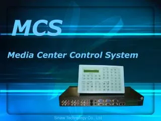
MCS-Magnum Chiller Logic www.mcscontrols.com REVISED-VER.L-1/1/2020
MCS-Magnum Firmware Versions • HVAC 17.XX - Chiller / Condensing Loop Water Units • CENT 17.XX- Centrifugal Chillers • REFR 17.XX - Refrigeration Storage Units • RTU 17.XX - Roof Top Package A/C Units • CPM 17.XX – Chiller Plant Controller
MCS-MAGNUM HVAC FIRMWARE(using HVAC 17.XX version) • Up to 20 compressors/refrigeration circuits • Up to 4 stages per compressor • All Compressor Types • Reciprocating • Screw • Centrifugal • Scroll • All Condenser Types • Air-cooled • Water-cooled • Evaporative-cooled
MCS-MAGNUM HVAC FIRMWARE • All Evaporator Types • Shell and tube • Flooded barrel • Plate heat exchanger • Dx air coil • Chilled Water Reset • Hard wired • Network • Automatic
MCS-MAGNUM HVAC FIRMWARE • Two Independent Electronic Expansion • Value (EXV) Controllers per Compressor • EXV Control for Compressor Subcooler • Pump Down / Disable switches • Low Suction PSI Unloading • High Discharge PSI Unloading • High Discharge Temperature Unloading • High Ampere Unloading & Holding • Low Evap Temp Unloading & Holding
MCS-MAGNUM HVAC FIRMWARE • Energy Efficient Compressor Staging • Chiller Water Pump Control (Primary / Standby) • Part Wind, Star Delta or Across the Line • (Fix Time or Dynamic) • Low & High Ambient Shutdown • English, Metric, or Mixed Sensor Readings • Compressor Auto Rotation • (Lowest Run Hours or First on/First Off)
MCS-MAGNUM HVAC FIRMWARE • User Logic-Custom Logic SI -config
MCS-Magnum Control Logic • The Control logic runs every second: • Reads all sensor inputs • Checks chiller safeties • Checks compressor(s) safeties • Runs unit state control logic • Runs once for each compressor: • Runs compressor state control logic • Runs evaporator EXV state control logic • Run subcooler EXV state control logic • Runs Condenser logic • Save input & outputs reading for graphic/trending • Write Relay and Analog Outputs
MCS-MAGNUM HVAC FIRMWARE • Look Up Tables ( shown in MCS-CONNECT) • Voltage Surge Curves Thermistor Curves • Curves in User Logic
State Control Logic • A State machine which operates based on the sensor inputs & configurations to control the unit • Switches states based on sensor inputs • The relay outputs and analog outputs are determined by the current state Simplified Unit State Control Logic ‘RUN/STOP SW OFF’ State UNIT IS LOADING UNIT IS UNLOADING UNIT IS HOLDING
State Control Logic • The MCS-Magnum runs four state controls: • Unit Control Logic • Compressor Control Logic • Evaporator EXV Control Logic • Subcooler EXV Control Logic • These states along with their relevant information can be viewed in the System Status window of MCS-Connect and status option on MCS-Magnum Keypad/LCD display
Viewing The Current State In MCS-Connect Unit Control Information Time Time in the current state Current State Ref Type Refrigerant type used Step Delay Value that is counted down. When this value reaches zero, the controller will determine if a change in the system capacity is required Wanted % Wanted compressor percentage Mode Mode is either Cooling, heating, or ice making Current Rate of Change Rate of change (up to 60 seconds) of the current controlling sensor Wanted/Actual Number of capacity steps Wanted On versus Number of capacity steps Actually On Current Controlling Sensor The current value of the controlling sensor Background color changes based on proximity to target temperature
Viewing The Current State In MCS-Connect Compressor Control Lead? The lead compressor will have a ‘Yes’ in this column Steps The current number of steps that are turned on for this compressor Current State PSI Diff Current calculated oil pressure FLA % Current percentage of full load amps Time Time passed in the current state
Viewing The Current State In MCS-Connect EXV Control Valve % The current percentage of each EXV Control On Suct. Supht The current value of the superheat for this compressor SuperHeat ROC The rate of change of superheat based on the time defined in the superheat target setpoint ADJ Delay When this value reaches zero, the controller will adjust the EXV based on the current status Current State Time Time passed in the current state
Viewing The Current State In MCS-Connect Additional Circuit Information
Viewing The Current State In MCS-MAGNUM CURRENT ‘STATE OF THE UNIT’ – Press PG HH:MM UNIT UNIT STATUS TIME IN THIS STATE HEADING CURRENT DATA FOR THE UNIT TARG SELECT PAGE UP/DOWN STATUS OF ‘COMP1’ – Press PG HH:MM UNIT BEING CONTROLLED COMPRESSOR STATUS TIME IN THIS STATE HEADING CURRENT DATA FOR THE UNIT SELECT PAGE UP/DOWN
Viewing The Current State In MCS-MAGNUM CURRENT STATUS OF ‘EXV 1’ – Press PG HH:MM EXV 1 STATUS TIME IN THIS STATE HEADING CURRENT DATA FOR THE UNIT TARG SELECT PAGE UP/DOWN CURRENT STATUS OF ‘COMP2’ HH:MM COMPRESSOR 2 STATUS STATE OF COMPRESSOR TIME IN THIS STATE HEADING CURRENT DATA FOR THE UNIT SELECT PAGE UP/DOWN
Unit States UNIT IN POWER UPSystem Reset or Power Returned (delay of 60 seconds or set point value) UNIT IS OFF System ready to run but no cooling capacity required UNIT IS HOLDING No change in capacity. UNIT UNLOADINGReducing chiller capacity - unloading. UNIT IS LOADINGIncreasing chiller capacity - loading UNIT UNLOADEDChiller is fully unloaded - all stage of cooling capacity are off. UNIT IS LOADEDChiller is fully loaded - all available stages of cooling capacity are on. RUN/STOP SW OFFRUN STOP sensor input is OFF - chiller turned off. OFF- NO EVAP FLOWFLOW SW sensor input is OFF - chiller turned off. SCHEDULED OFFOperating schedule is false. AMBIENT OFFLow Ambient Temperature - chiller turned off. UNIT IN LOCKOUTChiller locked out, all points except alarm point are OFF NO RUN- I/O LOSTLost communication Chiller locked out Chiller is fully loaded - all available stages of cooling capacity are on.
Compressor Control States LOST IO LOCKEDThis state is entered when the Capacity Control State is NO RUN- I/O LOST. CMP LOCKED OUTThe compressor is in a lockout state SWITCHED OFFThis state is entered when the compressor is off due to the pump down switch being on or the compressor flow switch being off. UNLD and PMPDWNThis state is entered when the pump down switch has been turned on or if this compressor is no longer Wanted On CMP ANTICYCEThis state is entered when the UNLD and PMPDWN state has been completed CMP OFF/READYThis state is entered when no capacity is required from this compressor, or the last state was CMP ANTICYCE, LOST I/O LOCKED, or SWITCHED OFF. OIL PMP LUBINGThis state is used to ensure proper oil flow prior to compressor startup CMP UNLOADED In this state the compressor is supplying its minimum cooling capacity. CMP IS HOLDING In this state, the required refrigeration capacity of system is being met; no movement of the slide valve is required. FAST UNLOADING For screw compressors only, this state is entered when the compressor is turned on. LO SUCT UNLOAD The capacity is being unloaded due to low suction pressure. LO SUCT HOLD Capacity is being held due to low suction pressure HI DISC UNLOAD The capacity is being unloaded due to a high discharge pressure, high discharge temperature, or low discharge superheat. HI DISC HOLD Capacity is being held due to high discharge temperature or pressure. SAFETY TRIPPED This state is entered when a safety trip occurs but a lockout is not generated. LO TMP UNLOAD This state is entered when the leaving liquid temperature is too low LO TMP HOLD This state in entered after releasing from LO TMP UNLOAD HI AMP HOLD This state occurs when a fully loaded compressor experiences an abnormally high amp draw. HI DIS TMP HLD This state is entered when a fully loaded compressor that has more than one step encounters a high discharge temperature. *Please see the MCS-Magnum manual for a complete list of compressor Control States
EXV & Subcooler States LOCKED OUT The compressor is in a Lockout state. EXV IS CLOSED The associated compressor is OFF and the valve is closed PRE-PMPDWN The valve has been in a closed state and the system is now requiring the valve action. EXV IN STARTUP At startup the valve will remain in this state for the time in Setpoint #20. At that time the state will be changed to holding, at this point the valve control logic will position the valve. EXV AT 100% This state will be entered when the valve opening reaches 100%. EXV IS HOLDING Refer to EXV Logic Chart, superheat is in control zone and ROC is acceptable. EXV IS OPENING Refer to EXV Logic Chart, superheat is in control zone but rising too fast, ROC less than 1.0. EXV IS CLOSING Refer to EXV Logic Chart, superheat is in the control zone and the rate of change is acceptable, ROC greater than –0.5. LOW SPRHT Refer to EXV Logic Chart, force a course valve adjustment. OPENING 4x Refer to EXV Logic Chart, superheat is above control zone. OPENING 2x Refer to EXV Logic Chart, superheat is in control zone but rising too fast, the ROC is greater than 1.0. LO PSI OPN Refer to EXV Logic Chart, state indicates that a low suction pressure condition exists. The suction pressure is less than Setpoint #77 “LOW SUCTION” plus twice the value of Setpoint #79 “LOW SUCT RELOAD” and the superheat is greater than Setpoint #9 “SUPERHT TRGT” plus twice the value of Setpoint #10 “SPRHT ZONE+-“. CLOSING 2x Refer to EXV Logic Chart, superheat is in the control zone and the rate of change is acceptable, the ROC is less than -0.5 and greater than -1.0. CLOSING 4x Refer to EXV Logic Chart, superheat is in control zone but falling too fast, ROC less than -1.0. HI LVL CLS This state indicates that a high refrigerant level. This state is entered if Setpoint #109 “HiRefLevel” is active and the superheat is greater than the value of this Setpoint. EXV MOP CLS Refer to EXV Logic Chart. Maximum operating pressure option is active and it is forcing the EXV to close. In this state the EXV valve’s opening will be reduced. EXV MOP HLD Refer to EXV Logic Chart. Maximum operating pressure option is active and it is forcing the EXV to hold.
Fixed Step Capacity • Unit capacity can be controlled by turning on or off: • Compressor(s) • Unloader(s) • Hot Gas Bypass The ‘Steps’ result from the relay turning ‘On or Off’ NOTE: The ± Control Zone should be large enough to eliminate cycling!
Variable Step Capacity • Unit capacity can be controlled by modulating: • Screw compressor slide • Compressor(s) with a VFD • Centrifugal with vanes • Digital Scroll The line results from modulating control
Zone Control • Target (Setpoint #1) • The desired value to maintain the controlling sensor at • Control Zone+ & Control Zone- (Setpoint #2 & #3) • Allowable range around the target Above the zone Unloaded On: Setpoint 151 setback Can be set to a number, or an offset of the target In the zone Upper Control Zone: Setpoint 1 plus 2 Target: Setpoint 1 In the zone Lower Control Zone: Setpoint 1 minus 3 Unloaded Off: Setpoint 151 Can be set to a number, or an offset of the target Below the zone Below the unloaded off limit
Chiller Control Decision Making • Set points establish target / control zone & unloaded off limit • How far from the target setpoint is controlling sensor input • How fast is the controlling sensor input moving to or away from the control target • The decision is then made to increase, decrease or maintain the cooling capacity • Capacity Control based on: • Entering temperature or one sensor input • Leaving liquid temperature or Suction PSI • Controlling sensor’s rate of change (ROC) is calculated
Rate of Change 120 miles 120 miles 4hours 4 hours of driving
Rate of Change In Chillers • Rate of change is used as a hold mechanism, which holds the capacity if the temperature is moving quick enough • Set points • #27 Max ROC- - Max. (negative) ROC above control zone. • #28 Max ROC+ - Max. (positive) ROC below control zone • #29 ROC Interval - ROC time period (in seconds, max 60s) • Setpoints #27 & #28 define the speed limits for the change in temperature
Applied Rate of Change Logic • Control above the zone Unit Control Starts in LOADING Current ROC > MAX ROC- Unit Control continues LOADING Current ROC ≤ MAX ROC- Unit Control HOLDS
Applied Rate of Change Logic • Control below the zone Unit Control Starts UNLOADING Current ROC < MAX ROC+ Unit Control continues UNLOADING Current ROC ≤ 1°F/s Unit Control HOLDS
Applied Rate of Change Logic • Unloaded off Logic • This state is entered when less capacity is required. Every second an adjustment is made to the step delay. When the delay reaches zero, the counter “steps wanted” on is decreased by 1. Unit continues UNLOADING Unit continues UNLOADING Unit UNLOADING UNLOADED OFF Unit OFF when below UNLOAD OFF VALVE
MCS Safeties • High Discharge Unloading, Holding, Trip Logic
List of Compressor Safeties • Low Suction Pressure • Unsafe Suction Pressure • High Discharge Pressure • High Discharge Temp • Low Oil Differential Pressure • Unsafe Oil Differential Pressure • High Oil Temperature • High Motor Temperature • Low Suction Super Heat • High Oil Seal Temperature • Dirty Oil Filter • Motor Fault • Emergency Stop • No Flow Protection • Freeze Protection • Low Amps (3 Phase) • High Amps (3 Phase) • Low Refrigerator Temperature
MCS Alarm Notifications • Alarms are displayed most current first • Reason for the alarm, for example “LOW SUCTION #1” a low suction alarm for circuit #1 was generated • Each alarm is date/time stamped e.g.“MAY 30 13:17:33” • All compressor safety have 120 seconds of run data • A lock out situation will not be created unless the same alarm occurs twice within a specified time, except Phase Loss, EMG/STOP, unsafe suction
Diagnostic Save Button • A Diagnostic save will do the following: • Saves the Config file • History Printout • Last 5 Lockouts Alarm Printout • Status Printout • Saves a Zip file to your computer and can • Auto Email zip file to: support@mcscontrols.com
Training Class Exercise 1 • Load the compressor to 100% capacity • Place the RUN/STOP in the RUN state • set the CHIL WTR sensor input higher than the target to simulate a demand • The Step Delay will be decremented by the distance from the current value to the target • When the Step Delay reaches zero, the system calculates the ± % change in capacity.
Training Class Exercise 2 Silmulate High Discharge Temperature Unloading For variable step compressors only. The capacity is being unloaded due to a high discharge temperature. The compressor will stay in this state until the pressure or temperature has dropped below the corresponding Setpoint. The system will then move to the HI DISC HOLD state. • Place the RUN /STOP in the RUN state • Discharge Temperature of compressor is 235 • Setpoint #87 HI DISC TEMP value is 230 • Setpoint #88 DISC TEMP UNLD value is 7.5 seconds • Setpoint #101 SAFETY HOLD DELAY is 120 seconds • The Magnum will begin unloading the compressor(s) with high discharge temperature until the temperature drops below the calculated value. During this time the circuit state is HI DISC UNLOAD. Once this temperature has been reached, the circuit state will be HI DISC HOLD. The compressor will remain in that state until the capacity control indicates that less capacity is needed or if the discharge temperature has returned to normal after the time in Setpoint #101 “SAFETY HOLD DELAY” has passed.