Network Layer in the Internet Model
Explore the role of the network layer in the Internet model. Learn about host-to-host delivery, addressing, routing, and the position of the network layer in an internetwork. Discover the different approaches to packet delivery and the importance of IP addressing.

Network Layer in the Internet Model
E N D
Presentation Transcript
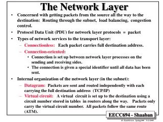
Role and Position of Network Layer • Network layer in the Internet model is responsible for carrying a packet from one computer to another • It is responsible for host-to-host delivery. • Position of network layer
Chapter 19Host-to-host Delivery :Interworking, Addressing, and Routing
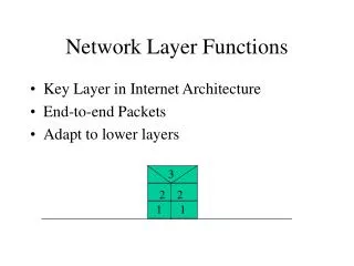
19.1 Internetworks • The physical and data link layers of a network operate locally
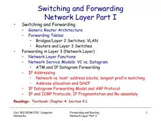
Switching • Virtual circuit approach – relationship between all packets belonging to a message is preserved – a single route is chosen, and all packets take that route • Datagram approach – each packet is treated independently of all others – thus, packets in the same message can take different routes, and possibly arrive out of order
Internet as a Connectionless Network • In a connection-oriented service, the source first makes connection with the destination before sending a packet. • They are sent on the same path in sequential order. • In a connectionless service, the network layer protocol treats each packet independently, with each packet having no relationship to any other packet.
19.2 Addressing • For a host to communicate with any other host • Need a universal identification system • Need to name each host • Internet address or IP address is a 32-bit address that uniquely defines a host or a router on the internet • The IP addresses are unique in the sense that two devices can never have the same address. However, a device can have more one address.
Notation • Binary notation 01110101 10010101 00011101 11101010 32 bit address, or a 4 octet address or a 4-byte address • Decimal point notation
Notation (cont’d) • Hexadecimal Notation - 8 hexadecimal digits - Used in network programming 0111 0101 1001 0101 0001 1101 1110 1010 75 95 1D EA 0x75951DEA
Classful Addressing • Occupation of address space • In classful addressing, the address space is divided into five classes: A, B, C, D, and E. • Finding the class in binary notation
Classful Addressing (cont’d) • Finding the address class
Classful Addressing (cont’d) • Finding the class in decimal notation
Example 4 • Find the class of each address: a. 227.12.14.87 b. 252.5.15.111 • 134.11.78.56 • Solution a.The first byte is 227 (between 224 and 239); the class is D. b. The first byte is 252 (between 240 and 255); the class is E. c. The first byte is 134 (between 128 and 191); the class is B.
Netid and Hostid • Each IP address is made of two parts; netid and hostid. • Netid defines a network; hostid identifies a host on that network.
Netid and Hostid (cont’d) • IP addresses are divided into five different classes: A, B, C, D, and E
Classes and Blocks • Blocks in class A • Class A is divided into 128 blocks with each block having a different netid. • Millions of class A addresses are wasted.
Classes and Blocks (cont’d) • Class B is divided into 16,384 blocks with each block having a different netid Many class B addresses are wasted.
Classes and Blocks (cont’d) • Class C is divided into 2,097,152 blocks with each block having a different netid. The number of addresses in a class C block is smaller than the needs of most organizations
Classes and Blocks (cont’d) • Class D addresses are used for multicasting; there is only one block in this class. • Class E addresses are reserved for special purposes; most of the block is wasted.
Network Address • The network address is the first address. • The network address defines the network to the rest of the Internet. • Given the network address, we can find the class of the address, the block, and the range of the addresses in the block • In classful addressing, the network address (the first address in the block) is the one that is assigned to the organization.
Network Address (cont’d) • Network address : an address with the hostid all set to 0s
A Sample Internet with Classful Address • Token Ring LAN (Class C), Ethernet LAN (Class B), Ethernet LAN (Class A) , Point-to-point WAN, A Switched WAN
Subnetting and Supernetting • Subnetting • A network is divided into several smaller networks with each subnetwork (or subnet) having its subnetwork address • Supernetting • Combining several class C addresses to create a larger range of addresses • IP Addresses are designed with two levels of hierarchy
Subnetting • Classes A, B, C in IP addressing are designed with two levels of hierarchy (not subnetted) • Netid and Hostid
Subnetting (cont’d) • Further division of a network into smaller networks called subnetworks • R1 differentiating subnets
Subnetting (cont’d) • Three levels of hierarchy : netid, subnetid, and hostid
Subnetting (cont’d) • Three steps of the routing for an IP datagram • Delivery to the site, delivery to the subnetwork, and delivery to the host • Hierarchy concept in a telephone number 031
Default Masks • When a router receives a packet, it needs to route it • Uses mask to determine the subnetwork address • Routers outside the organization use default mask • Routers inside use a subnet mask
Comparison of a default mask and a subnet mask • Number of subnets is determined by number of extra 1s in the subnet mask. • 2n = 23 = 8 subnets
Supernetting • A block of class x addresses • For example, • An organization that needs 1,000 addresses can be granted four class C addresses
Supernetting (cont’d) • 4 class C addresses combine to make one supernetwork
19.3 Routing • Next-hop routing
Routing (cont’d) • Network-specific routing • Don’t have an entry for every host connected to the same • physical network • Instead, only have one entry to define the destination network
Routing (cont’d) • Host-specific routing
Routing (cont’d) • Default routing
Static and Dynamic Routing Tables • Static routing table : containing information entered manually • Dynamic routing table • updating periodically using one of the dynamic routing protocols such as RIP, OSPF, or BGP • Whenever there is a change in the Internet, the dynamic routing protocols update all the tables in the routers.
IP Datagram (cont’d) • Version : for IP version4, it is 4 • Header Length : Defining the length of the datagram header in 4 byte words
IP Datagram (cont’d) • Differentiated Services • The first 6 bits : codepoint subfield (DSCP : differentiated services code point) • Values for codepoints
IP Datagram (cont’d) • Total Length : head + data • Defining the total length of the datagram including the header • Length of data = total length – header length • Limited to 65,535 (216 – 1) bytes • Encapsulation of a small datagram in an Ethernet Frame
IP Datagram (cont’d) • Fields related to fragmentation • Identification : 16 bit-field • Datagram id that is originated by the source host • Therefore, Source IP address + datagram id (identification) • All fragments having same identification number • Identification No. to be used for the destination in reassembling the datagram • Flags : 3 bit-field • D : Do not fragment (1) • If it can not pass the datagram through any available physical network, it discards the datagram and send ICMP error message to the source host • M : More fragment (0) • 0 : last fragment or only fragment
IP Datagram (cont’d) • Fragmentation offset : 13-bit field • Showing relative position of this fragment with respect to the whole datagram • Measured in units of 8 bytes : forcing hosts or routers that fragment datagrams to choose the size of each fragment so that the first byte number is divisible by eight
IP Datagram (cont’d) • Time to live • Used to control the maximum number of hops (routers) visited by the datagram • If the value is Zero, the routers discarded • If the source wants to confine the packet to the local network, it can store 1 in this field