
Hands-On Engineering with Analog Discovery: Bridging Math and Real World
Discover how to engage K-12 students in hands-on engineering with the Analog Discovery module offered by Washington State University. Build a program using robust, low-cost design kits and free resources to connect math and physics to real-world applications. With powerful educational tools and free support, empower students to develop critical thinking skills and practical knowledge. Join the workshop to explore the Analog Discovery's capabilities and ignite students' passion for engineering.

Hands-On Engineering with Analog Discovery: Bridging Math and Real World
E N D
Presentation Transcript
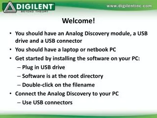
Welcome! • You should have an Analog Discovery module, a USB drive and a USB connector • You should have a laptop or netbook PC • Get started by installing the software on your PC: • Plug in USB drive • Software is at the root directory • Double-click on the filename • Connect the Analog Discovery to your PC • Use USB connectors
Washington State University Engineering Design in K-12 Education Tim Hanshaw ASEE June 2012
We need K-12 help Low Interest Declining Enrollment
A problem that affects us all 2-3 engineers leave the workforce for every new grad that enters
Roots of the problem • Lecture → homework → test → repeat approach has limited effectiveness • Students must be more engaged and involved in their own learning • Students who perform hands-on activities are more successful and interested in academic studies
Makers Are Learners Student with their own kits… • Learn more, learn faster, retain more • Score higher on tests • Complete more assignments • Use fewer resources • Enjoy their experience
Getting students involved and motivated • A reason to apply math skills • Develop abstract thinking skills (models vs. reality) • Creating projects in an “open” but well-defined environment builds confidence and knowledge Engineering provides an ideal framework for bridging math/physics and the “real world”: Bonus! Students develop skills with real/critical job applications!
Why Digilent? • Strong partnerships with leaders in technology (Analog Devices, Xilinx, Microchip, etc.) • World leader in educational kits • Products in more than 1500 universities worldwide, used bymore than 100,000 students/semester • Used in 90% of top schools • Active in PTLW, First, and academic research
Powerful Design Kits Built For StudentsRobust, low-cost, always current, use free tools*
Free Support Materials On-line textbooks - Lecture notes - Exercises & Lab Projects with solutions Complete Video Lecture Series - “Classroom” lectures - Lab/project videos - Special topics Reference Designs - FPGA, MPU, Analog
Help us help you • We will help you build a program at your school • All you need are low-cost PC’s, Digilent design kits, and a few electronic parts • We will help customize materials • What would you like to do in your classroom? • What kind of instructional resources would you want? • Drop by Digilent’s booth and chat
Let’s start the hands-on workshop • We will use the Analog Discovery in this workshop • The Analog discovery provides all capabilities necessary for test and measurement of analog circuits • Just add analog parts kit and WaveForms software! Developed with • $99 Student Price
Workshop Outline • Overview of tools we will use • Analog Discovery physical interface (connections to the electrical circuit) • Software used to control the Analog Discovery • Briefly recap goals and specific objectives of the workshop • Do some exercises to illustrate the Analog Discovery’s capabilities • Feedback appreciated relative to your assessment of its utility in YOUR classroom
WaveForms main window • Controls inputs/outputs • Analog instruments • Control power applied to circuits (Voltage, WaveGen) • Measure voltages (Scope) • Digital instruments • We will ignore these
Fixed Power Supplies • Connectors • Waveforms Voltage instrument
Variable Power Supplies (Waveform Generator) • Connectors • WaveForms WaveGen instrument
Voltage Measurement (Oscilloscope) • Connectors • WaveForms Scope Instrument
Remember our goals? • Get students excited about engineering and math • Show students the building blocks of electric circuits • Relate to familiar systems • Expose students to engineering design methods • Demonstrate basic physical laws using real devices and real tools • Establish foundations and framework for later studies • Intuit/understand physics, math, models that benefit students in many ways in many subjects
Analog Discovery’s Role • The Analog Discovery provides the ability to apply voltages (signals) to a circuit or device and measure the response • Allows us to test our designs! • Designs are based on mathematical models • Are abstract, can lack physical significance • Implementing and testing circuits allows us to: • visualize concepts • develop insight into mathematics • relate theoretical models to reality
Example: Home Heating System • Need to be able to design and test the individual components separately • Have to apply signals to the components and measure their response
Application to introductory courses • The overall circuit can be intimidating • However, the individual “bits” are within the capabilities of a novice to implement • Suggestion: Introduce the overall system in order to motivate implementation of simple sub-circuits • Students learn within the context of the familiar • Gives students a reason to care about the “boring” parts • Can sometimes sneak up on having them implement the overall (too complicated) circuit
How we will implement some “bits” • Need individual components • Need a way to interconnect them • Need to apply power and make measurements • Resistors, LED, speaker, capacitors… • Solderless breadboard • Analog Discovery module, WaveForms software and personal computer
“Solderless” Breadboard • Circuit connections are made by inserting leads into holes in breadboard • Five holes in each row are electrically connected • The channel isolates the rows on either side
Concept: Voltage Division • Traditionally, we present models (equations) and assume that the link to the real world somehow happens… • Voltage divider • Formula: • Boring…
Better! Lets build a useful/real circuit using this concept… • Use a resistor R1 whose resistance changes predictably with temperature • “Thermistor” • Then the voltage V2 changes with temperature! • We can use this to turn on the heater
Example 1a: Temperature Measurement • Connect circuit as shown • Connect Vp (+5V) to themistor • Connect ground ( , black wire) to resistor • Turn on Vp (Open Waveforms, click Voltage, Vp→Rdy, Power On) • Warm thermistor (grasp between thumb and finger) • Voltage across resistor increases!
Example 1b: Measure the temperature change • But how do we know that the temperature changed? • Oscilloscope provides a visual representation of the voltage • Add scope measurements to your circuit as shown • Open Scope instrument • Time Base: 5 s/div • C1 Offset: -2V • C1 Range: 500 mV/div • Click Run
Concept: Energy Conservation • “Green” (energy conserving) systems are a recognized important topic • We’ll do an example using a Light Emitting Diode (LED) • LEDs are intrinsically energy efficient • We can improve their efficiency by “pulsing” the power applied to them • We are essentially switching the LED on and off very rapidly • Aside: This approach can also allow us to dim lights
Square Wave • We can switch the LED on and off by applying voltage in the form of a “square wave” • The wave has “amplitude” and “period” • The frequency is the inverse of the period • High frequency signals have short periods; they vary rapidly
Light Emitting Diodes (LEDs) • LEDs emit light if sufficient voltage provided to them (e.g., more than 2V) • They burn out if too much current is applied (e.g., more than 100mA for simple LED).
Example 2a: Time varying voltage to LED • Connect circuit as shown • Apply square wave with “WaveGen” instrument • Min frequency 1Hz, Max frequency 200Hz • Set frequency = 1Hz, amplitude = 3V, offset = 0V • Increase frequency slowly, observe response
Example 2b: Measure LED voltage • Visually, LED response may not indicate actual circuit behavior at higher frequencies • Flashes too fast to perceive • Use oscilloscope to determine response • Connect leads as shown • Time Base: 50 ms/div • C1 Offset: 0 V • C1 Range: 1 V/div • Click “Run” • Repeat previous exercise
Example 2c: Reduce energy applied to LED • We saw that the LED appears to be “on” if the frequency of the square wave is high • We are saving energy! • Our square wave was “on” 50% of the time • Let’s reduce this and save more energy • In waveform generator, select Symmetry • Choose 20% and examine LED response • Repeat previous exercise • Try even smaller “on” times; now you have a dimmer
Now let’s look at audio applications • Students play instruments & listen to music • Sounds can give insight into the math • Sinusoids (math stuff) • f(t) = Acos(2ft+)
Example 3a: Creating sounds using AWG • Connect circuit as shown • Use “WaveGen” instrument to apply sinusoid to speaker • 2kHz, 2V amplitude, 0V offset • Set symmetry = 50%, change frequency ranges!
Concept: Modulation • Amplitude and frequency modulation are often used in communications (e.g. AM, FM radio) • We will get some insight into frequency modulation by generating sounds
Frequency Modulation • The frequency of one signal is varied according to the amplitude of a second signal
Example 3b: Modulated signals • Same circuit as before • Modulate with triangle wave: • choose “Advanced” tab • Set “Carrier” to sine wave (2kHz frequency, 2V amplitude, 50% symmetry) • Set “FM” to 2Hz triangle with Amplitude 50% • Run AWG1 • Try modulating with a square wave. • Should “toggle” between two tones
Example 3c: Play “scales” • Same circuit as before • Play “scales” • Text file provided with discrete values • AWG: Advanced • FM Custom Open File • Select scales.txt file • Set frequency = 500mHz , Amplitude = 100% • Carrier Standard Sine • Set frequency = 500Hz, Amplitude = 2V • Run AWG
Concept: Select frequencies to see and hear • Filters are electrical circuits which “pass” signals with selected frequencies • Common examples: • Bass, treble adjustments on audio systems • Speakers with both woofers and tweeters contain a crossover circuit which sends low frequencies to the woofer and high frequencies to the tweeter
Example 4: Low-pass filter • Add capacitor to circuit of Example 2 • The capacitor stores and releases energy • Basically, performs an integration • LED “sees” only slowly changing voltages • Low pass filter
Example 4: Low-pass filter • Add capacitor to circuit of Example 2 as shown to the right • Apply sine sweep • Type Sine, Sweep On, Damp Off • 1HZ 200Hz in 10 seconds • Amplitude = 4V • Monitor LED response as frequency changes
Thank You!Please come see us in our booth… www.analog.com/university