Download
1 / 16
160 likes | 296 Vues
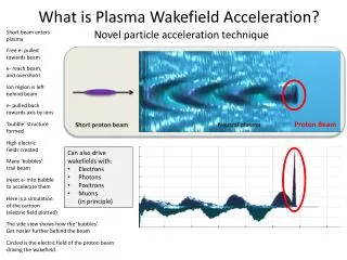
Recent Results on the Plasma Wakefield Acceleration at FACET E 200 Collaboration Beam loading due to distributed injection of charge in the wake reduces the transformer ratio Local ionization injection produces monoenergetic 20+ GeV bunches containing 20-40 pC charge.

E N D
Recent Results on the Plasma Wakefield Acceleration at FACET E 200 Collaboration Beam loading due to distributed injection of charge in the wake reduces the transformer ratio Local ionization injection produces monoenergetic 20+ GeV bunches containing 20-40 pC charge.
Why use a Rubidium source • Compared to previously used Li, the Rb plasma mitigates: • 1)beam head erosion problem - vetchα IP 1.73 • 2)emittance growth due to ion motion – use heavier atoms Singly ionized Rb plasma is created by the electric field of the beam. Periodic pinching of the drive beam can lead to ionization and injection of the second Rb electron into the wake. This distributed injection of dark current can load the wake and reduce the transformer ratio T = E+/E-
Experimental Set-up Foils of different thickness and composition used to increase the beam emittance
Unmatched Beam Undergoes Envelope Oscillations in Plasma Beam radius Rb Neutral Rb Density RbI RbII ArII Dark Current Region Ar Ar I No Dark Current RbII/ArII Distance (m) The electric field at the tightly focused regions of the beam can further ionize Rb and Ar
Emittance of the beam used to vary length of the wake and thereby vary energy loss • As the length increases so does the number of envelope oscillations the beam makes. • Each time the beam pinches down to a minimum it produces Rb2+. These new electrons (excess charge) are injected into the wake
Beam Loading reduces Transformer ratio <T> = E+/E- = ΔW+/ΔW-
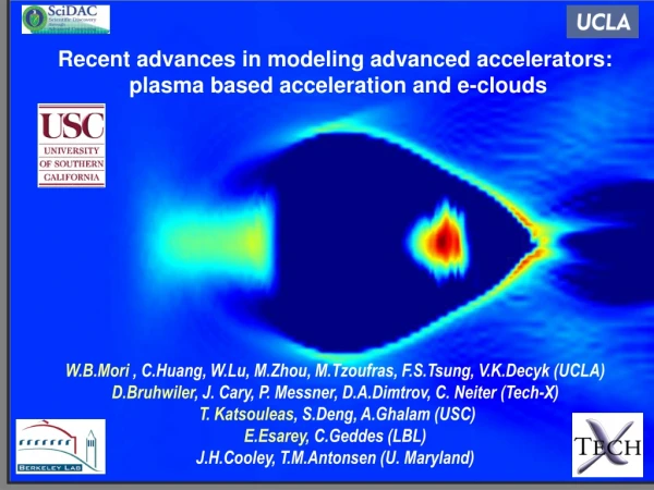
PIC Simulations Confirm thatBeam Loading by Distributed Injectionof Rb 2+ Electrons Reduced T Peak Accelerating field decreases from 44 GeV/m to 35 GeV/m due to beam loading
Summary • Use of Rb plasma explored for mitigating head erosion and ion motion • For the beam and plasma parameters used, ionization of Rb 1+ ions leads to injection of RbII electrons in the wake in distributed fashion • Beam loading of the wake reduces the average transformer ratio <T> from 1 to 0.85 • Simulations confirm the cause of beam loading as trapping of Rb II electrons. • Can we use ionization injection in a controlled manner to get narrow energy spread beams??
Use Ionization Injection to Generate Monoenergetic Bunches . Concept of Ionization Injection Into a PWFA Use Li plasma (not Rb) to ensure no dark current. Use He:Ar mix as buffer to control ionization-injection trapped charge
Simulations of Ionization Injection (Li plasma -50/50% He-Ar Buffer Gas)
Simulations Show MonoenergeticBunchlets with ~1% Energy spread
Experiments Used various Configurations Li Plasma with a) Pure He buffer (He electron injection) b) He buffer with 10%, 22% and 50% Ar (Inject Ar II &/ He ) c) He buffer with 30% Ne ( He or Ne injection) 2) Pure Ar gas column (Ar II or Ar III injection) All showed monoenergeticbeamlets under certain beam conditions
Mono-energietic bunchlets produced by ionization injection 50/50 Ar/He buffer gas, 30-cm long Li vapor flattop region 30 Accelerated tail electrons Bunchlets Energy (GeV) 24 20 6 images with spectometer set to image at 24 GeV Initial energy Bunchlets are from injected electrons (0 to 20+ GeV in 30 cm) Bunchlet energy gain ≥ gain of the FACET beam tail e-’s
Histogram of Trapped Charge • Mean charge about 30 pC The larger charge beamlets often had two blobs. The lower charge beamlets traversed a 1mm thick W foil placed to rule out coherent Cherenkov emission.
Energy Spread of MonoenergeticBeamlets Energy spread of ~ 0.5 GeV (FWHM) on a 25 GeVbeamlet. This corresponds to a ~ < 1% energy spread
Summary of Observations • Ionization Injection has produced narrow energy spread beamlets with energies on the order or exceeding the beam energy • 25 GeV energy gain from rest is observed in just 30 cm long Li plasma • Bunchlets typically have 30 pC of charge and a 1 % energy spread • Process appears to be robust with rms charge and energy spread variation of less than a factor of 2 and a success rate of ~ 80%.