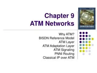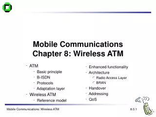
9. WIRELESS ATM
9. WIRELESS ATM. Anywhere, Anytime Access to ATM Networks. Voice, Data, Video, and Images in Any Combination, Anywhere, Anytime with Convenience and Economy. Fixed Wireless & Mobile Users Wireless Equipment. Problems Noisy Wireless Channels High BER. Wireless Channel

9. WIRELESS ATM
E N D
Presentation Transcript
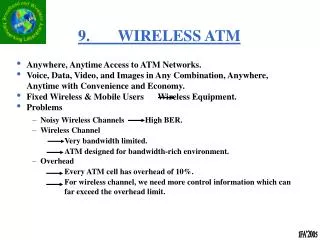
9. WIRELESS ATM • Anywhere, Anytime Access to ATM Networks. • Voice, Data, Video, and Images in Any Combination, Anywhere, Anytime with Convenience and Economy. • Fixed Wireless & Mobile Users Wireless Equipment. • Problems • Noisy Wireless Channels High BER. • Wireless Channel • Very bandwidth limited. • ATM designed for bandwidth-rich environment. • Overhead • Every ATM cell has overhead of 10%. • For wireless channel, we need more control information which can far exceed the overhead limit.
HLR ATM Network VLR MSC Base Station VLR: Visitor Location Register HLR: Home Location Register MSC: Mobile Switching Center (also ATM switch) Wireless ATM Network Architecture
Satellite Fixed ATM Network Wireless LAN FSC: Fixed Switch Center (ATM Switch)MBS: Mobile Base Station Wireless ATM in Digital Battlefield
Quality of Service (QoS) Parameters • Throughput • Delay • Jitter • Loss Probabilities • Probability of Dropping the Call • Expected BER; Packet Error Rate • Expected Disruption Time During Handoffs • Minimum or Maximum Level of Mobility • QoS Renegotiation Also in wired ATM network
Personal Mobility vs. Terminal Mobility User Terminal Network Wired Wireless Terminal Mobility Personal Mobility
Quality Critical Applications Time Critical Applications TCP UDP IP AAL Layer ATM Layer Error Control Medium Access Control Physical Layer (Wireless Channel) Protocol Stack For Wireless ATM IP Layer ATM Layer Link Layer
Specific Requirements for PHY Layer Low Speed Wireless PHY HIGH Speed Wireless PHY Frequency Band 5.15-5.35 GHz, 5.725-5.875 GHz 59 GHz - 64 GHz Cell Radius 80 m 10 - 15 m Transmit Power 10 – 20 mW 100 mW Frequency Reuse Factor 7 up to 12 Channel Bandwidth 30 MHz 150 / 700 MHz Data Rate 25 Mbit/s 155 / 622 Mbit/s Modulation 16 tone DQPSK 32 tone DQPSK MAC Interface par., transf. speed 87.5 Mbyte/s par., transf. speed 3.127 Mbyte/s Fixed Packet Length PHY header + MAC header + 4*ATM cells
System Architecture and Protocol Model Wireless Workstation User Applications (Quality-Critical Traffic) Host TCP/IP AAL Subsystem ATM Backbone Network ATM Sonet DL Subsystem Wireless Workstation Wired Line Wireless Link Host
Error Control Time Critical Applications FEC Hybrid ARQ Quality Critical Applications
Why FEC? • ATM HEC performance is too low for • wireless ATM. • High CLR and payload errors • Cell delineation problem • FEC (for Time-Critical Applications) • To correct channel errors at the expense of bandwidth by adding redundancy
Cells RS Outer Encoder Symbol Interleaver Conv. Inner Encoder Bit Level Interleaver Transmitter FEC Wireless Channel RS Outer Decoder Symbol Deinterleaver Viterbi Decoder Bit Level Deinterleaver Cells Receiver FEC Concatenated FEC Scheme
Why Hybrid ARQ? (for Quality Critical Traffic) ARQ provides high reliability at good and moderate channel qualities. The throughput drops rapidly, if the channel error rate is high as in wireless channels. Hybrid ARQ FEC first tries to correct the frequent error patterns. If it fails, then ARQ takes over. Hybrid ARQ Types Type I Hybrid ARQ scheme Type II Hybrid ARQ scheme: only additional parity bits are retransmitted to combine with the previous packet (incremental redundancy).
MT MT MT Medium Access Control for Wireless ATM Networks
Categorization of MAC Protocols • Based on Channel Organization • TDMA-Based MAC Protocols • CDMA-Based MAC Protocols • Random MAC Protocols • Hybrid MAC Protocols • Based on Duplex Mode of Uplink and Downlink • Time Division Duplex (TDD) (One Carrier Frequency) • Frequency Division Duplex (FDD) (Two Carrier Frequencies)
* Frequency Division Duplex (FDD) (Two Carrier Frequencies) • Uplink frequency carries traffic from terminal to BS while downlink frequency carries traffic from BS to terminal. • FDD allows almost immediate feedback from the BS enabling terminal to find out quickly if its contending reservation request was unsuccessful and a retransmission is necessary. • Thus, FDD impacts the delay encountered by user traffic as well as the resource availability of the wireless channel.
TDMA Based MAC Methods • Dynamic Packet Reservation Multiple Access (DPRMA), by Dyson and Haas in 1999. FDD • Mobile Access Scheme Based on Contention and Reservation for ATM (MASCARA), by Bauchot et al. in 1996, and Passas et al. in 1997. TDD • PRMA with Dynamic Allocation (PRMA/DA), by Kim and Widjaja in 1996. FDD • PRMA with Adaptive TDD (PRMA/ATDD), by Priscoli in 1996. TDD • Dynamic TDMA with Piggyback Reservation (DTDMA/PR), by Qiu et al. in 1996. FDD • Distributed Queuing Request Update Multiple Access (DQRUMA), by Karol et al. in 1995. FDD • Dynamic TDMA with TDD (DTDMA/TDD), by Xie et al. in 1995. TDD
Packet Reservation Multiple Access (PRMA) Protocol (Goodman’91) • Time is divided into slots of equal duration, and slots are grouped into frames. • Each slot in a frame is either “reserved” or “available”. • BS controls the upstream traffic and broadcasts a continuous stream of packetized information through the downstream channel • The status of a slot is provided in feedback information supplied by BS. • Terminals can send two types of information: “Periodic” information such as speech or “Random” information such as data. • Frame rate is identical to the arrival rate of the speech packets. • Uses S-ALOHA for time slot reservation and TDMA for data transmission.
Packet Reservation Multiple Access (PRMA) Protocol (Goodman’91) • A station contends for an available slot using S-ALOHA. • If transmission is successful, BS responds with an ACK message and the slot is reserved in subsequent frames until the terminal relinquishes it by leaving the slot empty. • A terminal with “random packets” contends for slots in the same way, but cannot reserve the same slot in a subsequent frame even after a successful transmission. • Thus, terminal must contend again for another available time slot. • For unsuccessful transmission, a terminal with “periodic” packets retransmits the packet with certain probability in subsequent unreserved slots until it receives an ACK signal from BS. • Similarly, a terminal with “random” packets retransmits a packet in unreserved slots with certain probability.
Packet Reservation Multiple Access (PRMA) Protocol (Goodman’91) Advantages: • Simple Disadvantages: * Upon congestion, the speech packet dropping rate and data packet delay both increase. * Feedback information may cause waste of bandwidth.
Request packet PRMA/DA header PRMA/DA trailer ATM cell … … … … 2 Na Nc Nv 1 1 2 1 1 2 Nd 2 Available slots CBR reservation slots ABR reservation slots VBR reservation slots PRMA/DA header PRMA/DA trailer ATM cell Wireless Packet PRMA/DA — Services and the Frame Structure • Supports Multimedia Traffic • Constant Bit Rate (CBR), Variable Bit Rate (VBR), Available Bit Rate (ABR). • Frame Structure • It is organized according to traffic types. • Downlink transmission is not considered. FDD Variable Variable Variable
Operation Procedures of PRMA/DA • Send Requests in Available Slots • Contention-based transmission. • Slotted ALOHA is used. • Reserve Time Slots for each Successful Request • Dynamic allocation algorithm is used to allocate time slots for CBR, VBR, and ABR connections. • The allocated time slots are reserved for the lifetime of a connection. • Dynamic allocation algorithm is also used for updating available time slots for the transmission of requests. • Transmit Packets in Reserved Time Slots • Since time slots are reserved, contention is free in this phase.
Contributions and Shortcomings of PRMA/DA • Contributions • Dynamic allocation of slots for each sub-frame. • Variable boundary can be easily implemented. • Bandwidth can be utilized efficiently. • Collisions can be resolved quickly • No mini-slots; Easy for synchronization. • Multiple traffic classes supported. • Shortcomings • A request packet has the same length as a data packet. • If traffic rate high, this would cause inefficiency. • No mechanism is used to dynamically update VBR resources. • VBR bandwidth is allocated according to the average rate. The bursty requirement has to rely on the leftover bandwidth. QoS of VBR cannot be guaranteed.
Downlink Period FH Period ContentionPeriod Uplink Period … … MPDU 1 MPDU 2 MPDU n PHY Hdr MPDU Hdr MPDU payload: Cell train (many ATM cells) 1 time slot n time slots MASCARA(Mobile Access Scheme based on Contention and Reservation for ATM) • Supports CBR, real-time VBR (rt-VBR), non-real-time VBR (nrt-VBR), ABR, UBR traffic. • Demand assignment scheme with contention based reservations. • Uplink subframe is divided into a contention period to transmit reservation requests or some control information, and uplink period for uplink data traffic. • Each period within a frame has a variable length depending on the instantanous traffic to be carried.
Operation Procedures of MASCARA • If a terminal has cells to transmit, it sends a reservation request either piggybacked in the MPDUs uplink period or in special control MPDUs sent in the contention period. • Base station schedules transmissions of the next frame according to reservation requests, arriving cells for each downlink connection, traffic characteristics and QoS requirements of all connections. • In the Frame Header of the downlink, BS broadcasts information which contains a descriptor of the current time frame (including the lengths of each period), the results of the contention procedures from the previous frame and the position of the slot allocated to each downlink and uplink connection. • To minimize PHY layer overhead, MASCARA uses the concept of a CELL TRAIN (a sequence of (1-n) ATM cells belonging to a terminal and having a common header). • Length of overhead plus that of the MPDU header is equal to one time slot, which is defined as the length of an ATM cell.
Priority Regulated Allocation Delay-Oriented Scheduling (PRADOS) * Assigns priorities for each connection according to its service class. * PRADOS combines priorities with a leaky bucket traffic regulator. • Regulator uses a token pool introduced for each connection. • Tokens are generated at a fixed rate equal to the mean ATM cell rate of each VC. • Size of the pool is equal to the maximum number of ATM cells that can be transmitted with a rate greater than the declared mean. • Starting at priority 5 and ending with priority 2, scheduler satisfies requests for connections as long as tokens and slots are available. • For every slot allocated to a connection, a token is removed from the corresponding pool.
Contributions and Shortcomings of MASCARA • Contributions • Cell train concept is used. • A novel scheduling scheme - PRADOS. • Dynamic TDD is implicitly implemented. • Multiple traffic classes are supported. • Shortcomings • With each request corresponding to a time slot, too many requests are transmitted in the protocol. This results in wasting bandwidth. • Large size of request packet results in reduction of good throughput. • Connection admission control (CAC) is separate from the MAC protocol. The overall performance of the integrated system is unpredictable.
Location Management Mobility Management in W-ATM Networks • Handoff Management Base Station A MT A is receiving a call ! How will the network deliver the call to A ?
TERMINAL MOBILITY (network should route calls to the MT regardless of its point of attachment) PERSONAL MOBILITY (users should access the network wherever they are; UPT (Universal Pers. Tel #)) SERVICE PROVIDER MOBILITY (allow user to roam beyond regional networks). Types of Mobility
Call Delivery (Paging) Location Update (Registration) Location Management
Too Many Location Updates Too Few Location Updates Low Paging Costs High Update Costs High Paging Costs Low Update Costs Cost Tradeoff
Location Areas (GSM) = Registration Areas (IS-41) Solution Registration Area Boundary Center Cell
Intra-Cell Inter-Cell Hard Handoff Soft Handoff Handoff Types
ATM Backbone Network ATM Switch ATM Switch Wireline connections to ATM switch Wireless connections to BS MT Cell BS W-ATM Architecture
LOCATION MANAGEMENT LOCATION SERVICE LOCATION ADVERTISEMENT TERMINAL PAGING TWO-TIER DATABASES VIRTUAL CONNECTION TREE INTEGRATED LOCATION RESOLUTION LOCATION REGISTERS MOBILE PNNI LOCATION MANAGEMENT TECHNIQUES FOR W-ATM
LOCATION SERVICE * Use of DATABASES to maintain records of MTs. * When location information is obtained from DATABASE, TERMINAL PAGING is used to deliver calls to MTs. * Requires signaling, querying and paging. LOCATION ADVERTISEMENT * No databases but location information is broadcast throughout the network.
(3) HOME ZONE (4) Home Tier Home Tier Home Tier Zone Manager (5) Visitor Tier Visitor Tier Visitor Tier (2) (1) CURRENT ZONE Location Service: Method 1: Two Tier Database (Akyol/Cox’96) PREVIOUS ZONE
Explanation: * Bi-level databases are distributed to ZONES throughout the network. * Each zone is maintained by a ZONE MANAGER controlling the zone’s location update procedures. * Each MT has a home zone where it is permanently registered. MT transmits a location registration request message to the new zone. Message contains User ID Number, authentication data and ID of the previous zone. Current zone manager determines the home zone of the MT from the previous zone ID. Current and home zone managers authenticate the user and update home user profile with the new location information. Home zone sends a copy of the profile to the current zone manager which stores the profile in the visitor tier of its database. Current zone manager sends a purge message to the previous zone manager so that user’s profile is deleted from the visitor tier before.
Location Advertisement: Method 1: Virtual Connection Tree (Veeraraghavan et.al.’97) Portable Base Station (PBS) Cell Boundary De-registration message MT’s Former position Registration message
VCT advertises location information via provisioned virtual paths. A collection of PBSs connected via provisioned VPs forms a connection tree. PBSs are equipped with switching capabilities and limited buffering capabilities. Trees are based on the mobility indications of the MT. Each PBS maintains a running list of resident MTs in its coverage area. Location registration occurs when MT is on/off or it moves to a new service area. On/Off case, MT sends a message to its local (current) PBS which then adds/deletes the MT to/from the service list. When MT moves to a new service area of a PBS, the PBS sends a de-registration message to the old PBS on behalf of the MT and enters the MT’s ID into its current list.
Location Service Location Advertisement Advantages Disadvantages Flexibility Database Admin Scalability Signaling Load Advantages Disadvantages No Paging No Scalability No Database Wasted Admin Bandwidth Comparison of LocationManagement Techniques
Handoff Management Multicast Connection Re-Routing Partial Connection Re-Routing Full Connection Re-Routing Route Augmentation InterWorking Devices Connection Extension Virtual Connection Tree Re-Routing Nearest Connection Node Re-Routing Hybrid Connection Re-Routing InterWorking Devices Connection Re-Routing Homing Base Station Re-Routing
Full Connection Re-Routing: Maintains the connection by establishing a completely new route for each handoff as if it were brand new call. Route Augmentation: Extends the original connection with a hop to the MTs next location. Partial Connection Re-Routing: Re-establishes certain segments of the original connection, while preserving the remainder. Multicast Connection Re-Routing: Combines the 3 techniques but includes the maintenance of potential handoff connection routes to support the original connection, reducing the time spent in finding a new route for handoff.
Comparison of Handoff Management Approaches Full Extension Partial Multicast Advantages Optimal route; existing methodology Fast; maintains cell sequence Maintains cell sequence; reduced resourceutilization Fast; maintains cell sequence Disadvantages Slow; inefficient resource re-assignment Wastes bandwidth; inefficient connection route Complex; added switch processing reqs Added buffering requirements; bandwidth pre-allocation
References: J. McNair, “Mobility Management Protocols for Wireless ATM Networks”,BWN Lab Technical Report, 1997. (Available on the WEB). I.F. Akyildiz, J. McNair, J. Ho, H. Uzunalioglu, W. Wang, “Mobility Management in Next Generation Wireless Systems”, Proceedings of the IEEE Journal, Vol, 87, No.8, pp.1347-1384, August 1999.