Pin-based tactile display
Pin-based tactile display .

Pin-based tactile display
E N D
Presentation Transcript
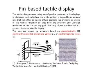
Pin-based tactile display The earlier designs were using reconfigurable pressure tactile displays. In pin-based tactile displays, the tactile pattern is formed by an array of pins that can either be in one of two positions (up or down) or vibrate in the vertical direction so that both the pressure and vibration modalities of the skin are engaged. The array of pins can be used as a graphic display or a Braille display. The pins are moved by actuators based on piezoelectricity [1], electrically-controlled pneumatic valves[2], or electromagnetic forces[3] [1] I. Poupyrev, S. Maruyama, J. Rekimoto, “Ambient Touch: Designing Tactile Interfaces for Handheld Devices”, 2002
Pin-based tactile display Electrically-controlled pneumatic valves [2] L. Yobas, D.M. Durand, G.G. Skebe, F.J. Lisy, M.A. Huff, “A Novel IntegrableMicrovalve for Refreshable Braille Display System”, 2003
Pin-based tactile display 6x6 tactile shape display that uses commercial RC servomotors to actuate an array of mechanical pins. The display has a maximum pin deflection of 2 mm along with a resolution of 4 bits. Pin spacing is 2 mm with a pin diameter of 1 mm. The display can accurately represent frequencies up to 25 Hz for small amplitudes. [4] C. R. Wagner, S. J. Lederman, R. D. Howe, “A Tactile Shape Display Using RC Servomotors”, 2002
Vibration-based devices It was constructed from an array of 64 closely packed piezoelectric actuators connected to a membrane. The deformations of this membrane caused an array of 112 skin contactors to create programmable lateral-stress fields in the skin of the finger pad. [5] V. Hayward, J.M. Cruz-Herna′ndez, “Tactile display device using distributed lateral skin stretch”, 2000
Vibration-based devices Using electro-magnetic resonator, the resonator consists of the solenoid coil and the permanent magnet. [6] T. Fukuda, H. Morita, F. Ara, H. Ishihara, H. Matsuura , “Micro Resonator Using Electromagnetic Actuator for Tactile Display”, 1997
Shape memory alloy (SMA) actuators Shape memory alloy wires can be used to provide actuation in a very small package. As current is passed through the SMA wire, it heats up and shortens by some 4-5%. Each actuator consists of a wire of 120mm length and 0.1mm in diameter [7]A sixty-four element tactile display using shape memory alloy wires [8]A tactile shape sensing and display system for teleoperated manipulation
Electrorheological(ER) and magnetorheological(MR) devices ER fluid: An ER fluid is defined as a colloidal suspension of a dielectric solid or polymeric particles in non-conducting solvents (the dispersed phase) and in an insulating base oil (the continuous phase), which under normal conditions behaves as a Newtonian fluid. However, when subjected to an external electric field, the relationship between the viscosity of the activated ER fluid and the intensity of the applied electric field initially rises rapidly, often in a square law manner, until a field strength of several hundred volts per mm is reached. The applied electric field induces dipoles, oriented parallel to the field, in the dielectric particles. These dipoles interact in such a way that they align themselves along the field direction and the ER fluid transforms to semi-solid.
ER actuator The probe is used to test the force. [8] P. M. Taylor, A. Hosseini-Sianaki, C. J. Varley, “An Electrorheological Fluid-based Tactile Array for Virtual Environments”, 1999
Electrorheological (ER) and magnetorheological (MR) devices MR fluid: Similar to ER fluids, magnetorheological (MR) fluids are suspensions of micron-sized ferromagnetic particles dispersed in different proportions of a variety of non-ferromagnetic fluids. Magnetorheologicalfluids exhibit rapid, reversible and significant changes in heir rheological (mechanical) properties when subjected to an external magnetic field. As with ER fluids, the MR fluids are also in liquid state without external stimuli. When MR fluids are subjected to a magnetic field, they behave as solid gels, typically becoming similar in consistency with dried-up toothpaste.
MR actuator [9] Chul-HeeLee, Min-GyuJang , “Virtual Surface Characteristics of a Tactile Display Using Magneto-Rheological Fluids ”, 2011
Ionic conductive polymer gel [11] Artificial tactile feel display using soft gel actuators, 2000
Soft actuator Silicone [12] SMD Pluggable Tactile Display Driven by Soft Actuator, 2012
Airborne Ultrasound [13] Non-contact Method for Producing Tactile Sensation Using Airborne Ultrasound, 2008 [14] Noncontact Tactile Display Based on Radiation Pressure of Airborne Ultrasound, 2010
SAW tactile display Slider When users explore the substrate without SAWs with their fingers via the slider- kinetic friction by the substrate is applied to the steel balls, thus creating sources of shear stress on the fingers’ surface at the positions of all the steel balls distributed spatially. By generating SAWs, we can descreasethe friction between the steel balls and the substrate. [15] SAW tactile display