Download
1 / 21
210 likes | 296 Vues
A detailed overview of See3PO, a robotic system designed for localization and navigation indoors. Discusses the components, functionalities, and advantages of the system.

E N D
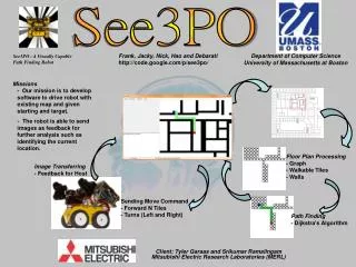
See3PO Frank Marino, Nick Wang, Jacky Yu, Hao Wu and Debarati Basu Department of Computer Science University of Massachusetts at Boston Tyler Garaas and Srikumar Ramalingam Mitsubishi Electric Research Laboratories (MERL)
The Anatomy of a See3PO • Cameras • Used by the Locator to get position • Local Brain • (currently being replaced) • Runs the local version of our program. • Communicates with the Host PC and with the Atom. • Atom Computer • Controls the Servos and the Wheels
Host PathFinder Floor Plan Processing Path Floor Plan Position Destination FP Image Floor Plan Host GUI Local Brain Robot Images FP Image Destination Commands Floor Plan Robot Images Position Locator Robot Host PC
Host – An overview • The Host class manages all other Host-Side processes • The User selects a Floor Plan Image from the GUI • Host sends this image to FloorPlanProcessing, which returns a FloorPlan. • This FloorPlan is sent to PathFinder to be converted into a graph. It is also sent back to GUI for display.
Host – An overview • Either the User (GUI) or the Locator sets the robot’s current Position, then the User (GUI) selects a Destination. • If using the Locator, the Host requests images from LocalBrain, and sends these to the Locator. • These points are sent to the PathFinder, which returns a Path of (X,Y) coordinates. • Host converts this Path to distinct Left/Right/Duration MoveComand objects, and sends them to the LocalBrain, one at a time.
GUI Status Screen Displays detailed messages from the Host Live Panel Displays a live view from the Robot • Floor Panel • The Main Interface: • Displays The Floor Plan • Allows the user to set: • Scale • Current Position • Destination • Displays the best Path • During execution, updates the Path and Position. Connection Status Instructions
Locator • Returns the current Position of the robot: Location(X,Y) • Facing (0 -359) • This position is used by PathFinder to create a Path, and to monitor and correct the robot’s progress while moving. • The only external inputs required are: • A Floor Plan Image • Robot Images from the robot’s two cameras • contd..
Locator • Advantages: • Precise • Works Indoors • Self-correcting • Recognizes changes • open/closed door • obstacles
Testing • Unit tests – are already in place • System tests – test plans are being developed
Robot Main parts of the robot Local Brain Receive commands from Host Control ATOM and cameras Send image back to Host ATOM Control wheels Cameras Wheels
Communication Protocol Commandsent from Host to localbrain (TCP) Commandsent from localbrain to ATOM (RS-232)
High Packet Loss Rate-ATOM Original Code main: “send speed to wheel every 20ms for i = 1 to 5 pulsout p12, rightSpeed pulsout p13, leftSpeed pause 20 next “read packet through COM port SERIN S_IN,i9600,… … goto main If the packet come in during the loop… Why????
How to solve that problem? Wheels need to get the pulse at least every 20ms to keep running. The longer the pulse, the faster the speed. Receiving speed data through COM port time Syntax pulsout pin, time pin: the I/O pin to use. time: the duration of the pulse in 0.5 microseconds increments.
Our Solution New Code ONINTERRUPT TIMERAINT,drive ENABLE TIMERAINT main: “read packet in from COM port SERIN S_IN,i9600,… … goto main drive: pulsout p12, rightSpeed pulsout p13, leftSpeed resume What did we implement? Interrupted by a timer every 20ms
Robot cannot move straight Original Code leftSpeed = 3000 rightSpeed = 3000 main: gosub drive gosub receive_command goto main drive: if initialized = 1 then for i = 1 to 5 pulsout p12, rightSpeed pulsout p13, leftSpeed pause 20 next endif return
How do we solve that Send different speed to the wheels Take the move forwards for example leftspeed=3179 rightspeed=3150 Note: the data comes from experiment test
Local Brain UI Debug mode show commands Movement control forward left stop .. Setting left and right speed as well as driving time
What will the robot have for version 1.0? Servo system can work Leave the robot anywhere in the science building, it can send pictures back to the host. After comparing the data in the host, the host can tell the robot where it is. The robot can receive the destination where the host tells.
What can we do if we still have time? Let the robot get something itself • Example: get coffee from a coffee machine and send it to one of our professors Use new wireless system (we use the wireless card, so it can just cover about 10 square meters) • Use local internet (like the UMass wireless) to make the robot move in the whole campus • Use new wireless like the iphone, make the robot to move further.
Questions? http://code.google.com/p/see3po/ Please feel free to ask questions.