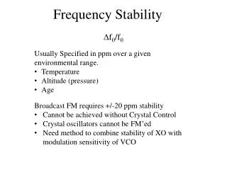
Frequency Stability
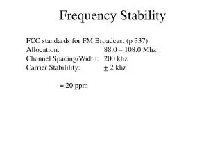
D f 0 /f 0 Usually Specified in ppm over a given environmental range. Temperature Altitude (pressure) Age Broadcast FM requires +/-20 ppm stability Cannot be achieved without Crystal Control Crystal oscillators cannot be FM’ed

Frequency Stability
E N D
Presentation Transcript
Df0/f0 • Usually Specified in ppm over a given environmental range. • Temperature • Altitude (pressure) • Age • Broadcast FM requires +/-20 ppm stability • Cannot be achieved without Crystal Control • Crystal oscillators cannot be FM’ed • Need method to combine stability of XO with modulation sensitivity of VCO Frequency Stability
Phase Locked Loop “Average” Phase Error Phase Error vm Crystal Oscillator f0 /N + VCO f0, ko, Df0 LPF ~ 5 Hz FMout + 1/N We will Study Phase Locked Loop dynamics in detail in Advanced Comm. This is the primary method for performing “coherent” demodulation.
FM Automatic Frequency Control Practical frequency control hardware always exhibits measurable frequency error, Df. Frequency Discriminator fdiscr , kd , D fdiscr VCO fo, ko, Dfo vin fout fin vout fout vout fo Dfo fdiscr ko fin kd vin D fdiscr Dfo D fdiscr _ + + + vin ko fout fin vout kd _ + fdiscr fo
Crosby Method of AFC Node variables are voltages Node Variables are frequencies + f* VCO fo, ko, Dfo vm fout N1 N2 + LPF ~ 5 Hz ftest = N1f0 Frequency Discriminator fdiscr , kd , D fdiscr Crystal Oscillator fxo , Dfxo BPF ~ fdiscr Low pass filter prevents correction voltage from trying to follow the audio frequencies in the modulation voltage Band pass filter, centered on fdiscr , selects only the “difference” frequency coming out of the mixer
Crosby Loop Analysis Dfo + f* + + vm ko fout N1 N2 + + VCO fo ftest = N1f0 D fdiscr _ _ + + + fxo kd _ + Frequency Discriminator fdiscr Dfxo fd = (fxo+ Dfxo) – f* Must find transfer function(s) in order to determine effect of drift (Df) terms on fout.
Dfo + f* + + vm ko fout N1 N2 + + fo ftest = N1f0 Dfdiscr _ _ + + + fxo kd _ + fdiscr Dfxo There are seven inputs to the loop, therefore there are seven Transfer Functions! …(fo, fd, and fxo are constants, so we don’t care about theirs) • Giis forward gain from input i to output (fout). • L is Loop Gain: Total Drift of fout is the sum of the magnitudes of the drifts of fout due to each Df term.
Dfo + f* + + vm ko fout N1 N2 + + fo ftest = N1fo Dfdiscr _ _ + + + fxo kd _ + fdiscr Dfxo To find “open loop” responses to drift terms (“ before correcting for feedback improvement”), place the switch in the test position. Now the response to each Df term is just the forward gain from it’s input to fout.