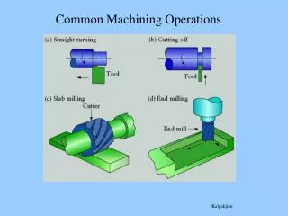
Machining Module 5: Lathe Setup and Operations
Machining Module 5: Lathe Setup and Operations. Parallel (Straight) Turnning. Parallel turning is to move the cutting tool parallel to the longitudinal axis of the workpiece in order to reduce its diameter. It has cutting edge on left side It moves from right to left.


Machining Module 5: Lathe Setup and Operations
E N D
Presentation Transcript
Parallel (Straight) Turnning Parallel turning is to move the cutting tool parallel to the longitudinal axis of the workpiece in order to reduce its diameter.
It has cutting edge on left side It moves from right to left Right Hand turning tool
Roughing and finishing operations Rough Turning Finishing Turning Is to bring the workpiece to the required size and to produce a good surface finish. • Rough turning is used to remove most of the excess material as quickly as possible to reduce the work diameter.
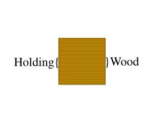
Mount the work piece Mount the work securely in a three jaw universal chuck, with no more than three times the diameter extending beyond the chuck jaws. Drilled Centre could be used to help in accurately centering the workpiece by using the tailstock
Setting the machine Set the cutting tool to the center by using tail stock Set the turning speed within a range of (350 – 400 RPM)
Taper Turning A process used to increase or decrease the diameter of the workpiece in a uniform rate.
Taper angle calculation Taper angle (α) = 45
Taper angle calculation • Tan α = opposite / adjacent • Opposite= 40-20 /2 = 10 • Adjacent = 16 • Tan α = 10/16 = 0.625 • α = 32
How to produce taperd surface 1)Offsetting the tailstock This method is mainly used for longtapers.
How to produce taperd surface 2)Using the compound rest This method is mainly used for short tapers. Use the compound rest hand wheel to feed the tool during taper turning cutting.
Grooving (Recessing) process: It is the process of cutting a groove to specific depth and width.
Grooving (Recessing) process: Set the lathe to one-half the turning speed, (about 200 -250 RPM) Recessing tool
Threading process It is a process of cutting helical or spiral ridge. External thread Internal thread
Thread applications 1. To fasten devices 2. To increase force. • 3. To provide accurate measurement, as in a micrometer. 4. To transmit motion; the threaded lead screw on the lathe causes the carriage to move along.
Types of threads 1. Right-hand thread: Right-hand thread is a type of threaded section onto which a nut is threaded (to be tightened) in a clockwise direction. 2. Left-hand thread: A left-hand thread is a type of threaded section onto which a nut is threaded (to be tightened) in a counter clockwise direction.
Thread Terminology • The major diameter: is the largest diameter of the thread. • The minor diameter : is the smallest diameter of the thread. • The pitch diameter: is the diameter of an imaginary cylinder that passes through the thread at a point where the groove and thread widths are equal. • The pitch (P) : is the distance from a point on one thread to a corresponding point on the next thread,. • The angle of thread: is the included angle between the sides of a thread
Because of the wide range of applications. Threads are designed in different forms as shown below: Metric thread Acme thread Another common type of thread is square thread which is used to transmit high force like screw jack.
Parts used in thread cutting 1. Center gauge: used to set the threading tool at right angle with the work 2. Screw pitch gauge: Used to check the thread pitch. 3. Use quick change gear box to select the required pitch
The thread shown below is M20x1.5outer diameter= 20 mm , pitch=1.5mm, thread angle= 60, Depth =0.974 Threaded workpiece Thread on technical drawing
Thread cuttingThe tool feed must equal to the thread pitch. Use gear box to select the required pitch. Engage the split-nut lever for automatic feed.
Drilling is to make a hole having a specific diameter and depth in a solid material. Drilling Process Drillingas shown on technical drawing.
Centre drilling is to make a small conical shape . Centre drilling Process Centre drilling as shown on as shown on technical drawing. Centre drilling is required for. 1.to guide the drill 2. to provide seat for tailstock centre.
Polishing:Is a finishing operation performed on the workpiece to improve the surface quality. Aluminum oxide abrasive cloth should be used for polishing most ferrous metals. Silicon carbide abrasive cloth is used on nonferrous metals.
Boring and parting off Boring is the operation of enlarging a hole with a single point cutting tool Parting off
Knurling and Grinding Knurling: it is a process of embossing a pattern on the cylindrical surface to provide a better grip . Grinding: can be done if the Lathe is equipped with an electric grinding attachment.