
CFEB Input Cable Labeling and Installation Scheme for Ground Lug Connections
This document outlines the cable labeling scheme and installation order for the CFEB Input Cable Assembly, specifically for Ground Lug connections. It details the correct sequence of connections, starting from Layer 1 to Layer 6, ensuring systematic installation. The flag connector is to be connected first on the ground lug of the chamber, followed by the chamber end connector, and finally the CFEB end connector. The straight ground lug must connect to the nearest grounding lug at CFEB Pin One. Important considerations for labeling and installation are included.

CFEB Input Cable Labeling and Installation Scheme for Ground Lug Connections
E N D
Presentation Transcript
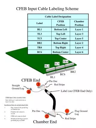
TR4 TC5 TL3 BR2 BC6 BL1 TL3 CFEB Input Cable Labeling Scheme CFEB End Pin One 3 Red Stripe Straight Ground Lug Label (on CFEB End Only) 4 CFEB Input Cable Assembly Order Start with layer 1 and work down to layer 6 in order. • Installation Order for an Individual Cable • Flag connector On ground lug of chamber first. • Chamber end connector second. • CFEB end connector third • Straight ground lug to nearest grounding lug on CFEB Pin One 1 Flag Ground Lug 2 Red Stripe Chamber End