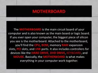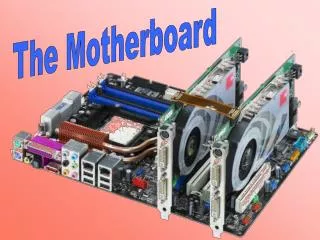
The Motherboard
The Motherboard. Objectives. After completing this section you will: Understand the major components on a motherboard including the microprocessor, chipset, math coprocessor, and expansion slots.


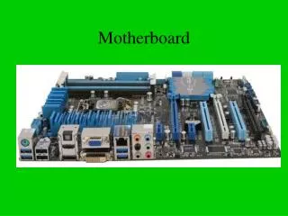
The Motherboard
E N D
Presentation Transcript
Objectives After completing this section you will: • Understand the major components on a motherboard including the microprocessor, chipset, math coprocessor, and expansion slots. • Understand the basic operation of a microprocessor and what issues must be considered when upgrading it. • Recognize and identify the microprocessor. • Understand the differences among the various architectures and buses. • Recognize different expansion slots. • Recognize an adapter’s architecture or bus.
Microprocessor Overview • Microprocessor (or processor) • CPU (Central Processing Unit) • Clones – IBM compatibles • PC – Stands for Personal Computer, another name for the microcomputer. • We will focus on compatibles (or non-Apple computers) because they make up the majority of computers in use today. • Because Intel and AMD are the microprocessors primarily used in today’s computer industry, they are the examples covered extensively in this material.
Microprocessor Basics • Bit – Either a 1 or 0. All microprocessors use 1s and 0s to calculate or interpret information. • Byte – Eight bits grouped together, the letter A looks like 01000001 to the processor. Each character on the keyboard appears as one byte (or eight bits) to the CPU. Denoted by the letter B, thirty-two bytes is 32B. • Kilobyte – Approximately 1,000 bytes (1,024 exactly, but rounded off by the industry to the nearest thousand for ease of calculation). Shown as K or KB, tenkilobytes is shown as 10K or 10KB. • Megabyte – Approximately one million bytes and referenced by M or MB. 540 megabytes is shown as 540M or 540MB. • Gigabyte – Approximately 1 billion bytes (1,073,741,824) and written as 1G or 1 GB.
Microprocessor Basics Motherboard – Table #1
Microprocessor Basics • Gigahertz (GHz) Hertz is a measurement of cycles per second (or frequency). One hertz equals one cycle per second. One megahertz (1MHz) is equal to one million cycles per second, one gigahertz (1GHz) is one billion cycles per second. For comparison, the 8088 microprocessor ran at 4.77 MHz, today’s CPUs run at over 2 GHz! • Register size – The number of bits processed at one time by the processor. Counted in multiples of 8 bits, such as 8-, 16-, and 32-bit register size. Sometimes referred to as word size by the computer industry. Intel’s 8086 processor’s word size was 16 bits or 2 bytes. Most microprocessors today have 64-bit or 128-bit register sizes. • Bus – Electronic lines to move the 1s and 0s inside the computer.
Microprocessor Basics • Internal data bus – Moves the 1s and 0s inside the microprocessor. In the 8086, there are 16 separate electronic lines, each carrying one 1 or one 0. The word size and internal data bus were the same size, 16-bit. • External data bus – Used to connect the microprocessor to adapters, storage devices, and peripherals. Also called the external data path, these lines connect to ports and expansion slots. The Intel 8088 had an 8-bit external data bus. Today’s CPUs have 64-bit external data paths. • Today’s microprocessors have 64-bit or 128-bit internal data bus lines and external data paths.
Microprocessor Basics Internal and External Data Buses Motherboard – Figure #1
Microprocessor Basics Intel Microprocessors Motherboard – Table #2
Microprocessor Basics • Pipelines – Separate (multiple) internal buses that operate simultaneously. This allows tasks and instructions to be broken down into smaller and more numerous parts, which permits the CPU to act on them more quickly and efficiently, improving computer performance. • SEC (Single Edge Contact) cartridge – Used with an Intel Slot 1 connector on Intel’s Pentium II microprocessor to reach speeds of 300MHz. • SEPP (Single Edge Processor Package) cartridge – Similar to the Pentium II SEC and used with the Intel Celeron processor.
Microprocessor Basics Intel Microprocessors Motherboard – Figure #2
Microprocessor Basics Motherboard – Figure #3
Microprocessor Basics Intel CPU Sockets and Slots Motherboard – Table #3
AMD Processors • AMD (Advanced Micro Devices, Inc.) – Produces a microprocessor similar to the Intel processors. • Super 7 Socket – Redesigned Socket 7 that allows for higher bus speeds (66 to 95 or 100MHz). Super 7 motherboards allow higher CPU speeds, support for AGP and Ultra DMA hard drives, and have advanced power management features. • Socket A –462-pin PGA socket for the AMD Athlon and Duron CPUs. • Slot A – Used by early AMD Athlon processors similar to Intel Pentium III, but they are not interchangeable.
AMD Processors AMD’s Socket A Motherboard – Figure #4
AMD Processors AMD Athlon Motherboard – Figure #5
AMD Processors AMD CPU Sockets and Slots Motherboard – Table #4
MMX, SSE, and 3DNOW! • MMX –A microprocessor technologyfrom Intel that adds 57 instructions to an Intel processor to help with multimedia and communications software. • SSE(Streaming SIMD Extensions) – Intel’s processor technology that speeds up 3-D applications by allowing instructions to be used by multiple data items. There are 50 instructions allowing floating-point calculations to occur simultaneously. • 3DNOW! – 21 instructions and support for SIMD added to an AMD processor for 3-D applications.
Processor Speeds and Cooling • Microprocessors and math coprocessors come in many speeds and this is measured in gigahertz (GHz). Hertz is a measurement of cycles per second (or frequency). One hertz equals one cycle per second. One megahertz (1MHz) is equal to one million cycles per second, one gigahertz (1GHz) is one billion cycles per second. • The faster the microprocessor runs, the hotter it gets. Many processors now have heat sinks (metal bars protruding from the CPU to form a basic radiator) or small fans for cooling. In many cases, today’s processors have both. Some systems even have multiple fans to prevent damage to the processor and internal components due to the amount of heat being generated. • Liquid cooling system – liquid is circulated through the system, including through a heat sink that is mounted on the CPU. It allows higher clock speeds and is quieter than a fan.
Processor Speeds and Cooling Microprocessor Speeds Motherboard – Figure #6
Processor Speeds and Cooling Microprocessor Fan and Heat Sink Motherboard – Figure #9
Processor Speeds and Cooling • Other things to know when determining processor speeds: • Jumper – Small metal connector with a plastic cover used to connect two metal pins together. Configuring the jumpers on a motherboard will change the settings on that board. • Multiplier – A number that is multiplied by the bus speed to determine the CPU speed. • Example: 60MHz bus speed x 1.5(multiplier) = 90MHz CPU
Processor Speeds and Cooling CPU with Heat Sink and Fan Motherboard – Figure #10
Processor Speeds and Cooling JP1 Jumper Block with Pins 1 and 2 Jumpered Together Motherboard – Figure #11
Cache Memory • Cache memory – A fast type of memory designed to increase the speed of microprocessor operations. • L1 (Level one) cache – Cache memory that is located inside the microprocessor. • Write-through cache – The microprocessor writes 1s and 0s into the cache memory at the same time as regular memory. • Write-back cache – The 1s and 0s are written to regular memory when the microprocessor is not busy. It is more efficient than write-through cache. • L2 cache – Cache memory that is on the motherboard for Pentium and lower processors. Starting with the Pentium Pro processor, the L2 cache is inside the processor packaging and known as on-die cache.
Cache Memory • L3 cache – L1 and L2 cache are included with the processor packaging. • COAST (Cache On A STick) – Cache chips on the motherboard that resemble a small SIMM. • DIB (Dual Independent Bus) – Two buses used for the processor to communicate with motherboard components. • FSB (front side bus) – connects a CPU to the motherboard components. • Back side bus – connects the CPU to the L2 cache.
Cache Memory Front Side Bus Motherboard – Figure #12
Microprocessor Study Guides Intel Microprocessor Study Table Motherboard – Table #6
Microprocessor Study Guides AMD Processors Motherboard – Table #7
Microprocessor Upgrade Overview • Always refer to the motherboard’s documentation when upgrading the processor. It allows you to choose the proper processor and prevent damage to the processor and motherboard. • VRM (Voltage Regulator Module) – Provides the appropriate voltage for microprocessors. It is usually found on Socket 7 or Socket 8 for Pentiums.
Installing and Overclocking Microprocessors • Always refer to the motherboard manuals for the installation steps to upgrade or install the processor. Your book contains general instructions for upgrading and installing the microprocessor beginning on page 2-25. • Overclocking – Changing the front-side bus speed or the multiplier to boost the CPU speed or system speed. This can cause damage to the CPU, motherboard, or other components.
Installing and Overclocking Microprocessors Computer Case Auxiliary Fans Motherboard – Figure #14
Dual Processors • Adding another (or dual) processor can greatly enhance computer performance. Most home and business users do not require an additional processor, however most servers do. • Follow all manufacturers documentation on selecting an additional processor, installing it, and configuring the motherboard with dual processors. • Its important to add RAM if possible when adding a second processor. Put in as much RAM as the customer can afford to improve performance. A general rule of thumb is to double the RAM when adding a second processor.
Motherboard Troubleshooting • Motherboard and power problems are probably the most difficult things to troubleshoot. A good general list of motherboard troubleshooting tips can be found on page 2-29 in your book.
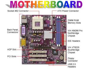
Expansion Slots • Expansion slots allow adapters to be installed into the motherboard to add capabilities to the PC. • Technicians must be able to identify expansion slots and distinguish between the adapters that use them. • The technician must be able to install the proper adapter in the correct expansion slot and configure both correctly.
ISA (Industry Standard Architecture) • ISA (Industry Standard Architecture) – The oldest expansion slot that is configured in 8-Bit and 16-Bit slots. • Also referred to as the AT bus. • Operates at 8MHz, although some manufacturers reliably achieve a throughput of 10 MHz. Motherboard – Figure #15
EISA (Extended Industry Standard Architecture) • EISA (Enhanced Industry Standard Architecture) – 32-bit expansion slot that is the same length as an ISA slot and twice as deep. • A non-proprietary architecture developed by a group of nine vendors in response to IBM’s proprietary MicroChannel Architecture. • A 32-bit, 10MHz standard that also allows ISA adapters to operate in the expansion slots. • This standard was never as successful as the designers hoped.
PCI (Peripheral Component Interconnect) • PCI (Peripheral Component Interconnect) – The most popular expansion slot that is configured in both 32-bit, 33MHz and 64-bit, at 33MHz and 66MHz. • A new standard is the PCI-X which can operate at 66MHz, 133MHz, 266MHz, and 533MHz. PCI-X 1066MHz is being developed. • PCI adapters are configured with software and the standard supports bus-mastering, which allows an adapter to take over the external bus from the CPU and execute operations with another bus-mastering adapter without going through the processor.
PCI (Peripheral Component Interconnect) PCI-X Block Diagram Motherboard – Figure #17
PCI (Peripheral Component Interconnect) 3.3 Volt and 5 Volt PCI Expansion Slots Motherboard – Figure #18
PCI (Peripheral Component Interconnect) Motherboard – Figure #19
Mini PCI • Mini PCI – 32-bit, 33MHz standard was developed to allow PCI upgrades and interface cards to be added to laptops, docking stations, and printers. Mini-PCI cards have 3 form factors; Type I, Type II, and Type III. Mini PCI Adapter Installed in Laptop Motherboard – Figure #20
AGP (Accelerated Graphics Port) • AGP (Accelerated Graphics Port) – 32-bit bus interface for graphics adapters developed from the PCI bus. • It speeds up 3-D graphics, 3-D acceleration, and full-motion playback. • Allows the video adapter to directly access RAM on the motherboard when needed. • The video subsystem is isolated from the rest of the computer. • In order to implement AGP, the motherboard must have an AGP expansion slot, the chipset must support AGP, and an operating system that supports AGP must be installed. • Some motherboards will allow changing the amount of memory AGP can use. The amount normally used is 64MB, configured through BIOS settings, and referred to as the AGP Aperture.
AGP (Accelerated Graphics Port) AGP Versions Motherboard – Table #8
AGP (Accelerated Graphics Port) AGP Expansion Slot Motherboard – Figure #22
More Motherboard Connectors • AMR (Audio/Modem Riser) – Connector on the motherboard for combination audio and modem adapters without taking up a PCI slot. • CNR (Communications Network Riser) – Intel’s design that allows the integration of network, audio, and modem functions. It shares a PCI slot and is located beside or between other motherboard expansion slots. • ACR (Advanced Communication Riser) – Technology that supports audio, modem, networking, and DSL modems. It was developed by a group of companies including AMD, VIA Technologies, Motorola, and 3Com.
Future Buses • HyperTransport – AMD’s futuristic I/O architecture in which a serial-link design allows devices to communicate in a daisy chain fashion. • InfiniBand – A futuristic I/O architecture wherein point-to-point device connections are made through a switching fabric. • HCA (Host Channel Adapter) – Connects memory to a switch fabric and is used in the InfiniBand bus architecture. • TCA (Target Channel Adapter) – An adapter that connects end devices to the switch fabric and is used in the InfiniBand architecture. • RapidIO – A futuristic I/O architecture that supports interconnections for chip-to-chip, board-to-board, and device-to-device.
Proprietary Expansion Slots • Some older computers have an expansion slot built into the motherboard that are neither ISA nor PCI. These are proprietary expansion slots that only fit proprietary adapter cards. These are only available from the expansion slot manufacturer (if still supported) and usually expensive.
USB (Universal Serial Bus) • USB (Universal Serial Bus) – Allows connection of up to 127 external devices without degradation of speed. Can be used by many types of devices as long as the operating system supports USB. • Original USB includes two speeds: • 1.5Mbps for keyboards and mice. • 12Mbps for modems, CD/DVD drives, printers, scanners, monitors, and digital cameras. • USB version 2.0 supports speeds up to 480Mbps for videoconferencing cameras, higher resolution printers and scanners. It is backward compatible for USB 1.1 devices. • USB has two types of USB ports and connectors – Type A and Type B.
USB (Universal Serial Bus) USB Type A and Type B Connectors Motherboard – Figure #27