Text proposal for using receiver information
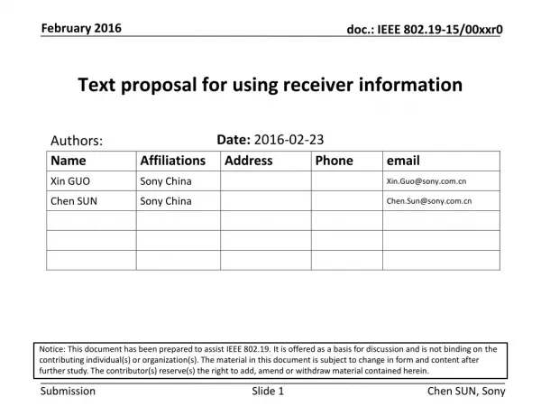
Text proposal for using receiver information. Date: 2016-02 -23. Authors:.

Text proposal for using receiver information
E N D
Presentation Transcript
Text proposal for using receiver information Date:2016-02-23 Authors: Notice: This document has been prepared to assist IEEE 802.19. It is offered as a basis for discussion and is not binding on the contributing individual(s) or organization(s). The material in this document is subject to change in form and content after further study. The contributor(s) reserve(s) the right to add, amend or withdraw material contained herein. Chen SUN, Sony
Abstract • In 16/23r0 we have proposed adding receiver information in the IEEE 802.19.1a system in order to improve the coexistence performance • As an example, we have shown that knowing the FBMC overlapping K factor of FBMC we can adjust the transmit power to assist the successive interference cancellation (SIC) receiver. • This document provides the proposed changes on the current IEEE 802.19.1 standards for adding receiver information Chen SUN, Sony
Why we need receiver information • PCAST: “Recommendation 3.1: The Secretary of Commerce working through the National Telecommunications and Information Administration (NTIA), in cooperation with the Federal Communications Commission (FCC), should establish methodologies for spectrum management that consider both transmitter and receiver characteristics to enable flexible sharing of spectrum. ” [1] • IEEE 802.19.1-2014 does not specify exchanging of receiver information for coexistence management Chen SUN, Sony
What is receiver information • Receiver type • Linear receiver such as zero forcing • Nonlinear receiver such as successive interference cancellation • … • Modulation information • OFDM • FBMC • … • Filter characteristics • ACS (existing) • Filter overlapping factor • … Chen SUN, Sony
Use case • Consider a CM managing multiple wireless networks (WSOs). • The CM knows that some WSOs on the same channel. • Some WSOs employ SIC at the receiver side. • If the WSO transmitter employ FBMC, the CM can control or suggest the WSO transmitter to use different FBMC overlapping factors so that their transmit power difference is maximized. • By maximizing the difference, the SIC performance can be improved. Chen SUN, Sony
Procedure utilized (1/2) • 5.2.2.1 WSO registration procedure Chen SUN, Sony
Procedures utilized (2/2) • 5.2.10.1 WSO reconfiguration procedure Chen SUN, Sony
Updated message 1 --Installation parameters InstallationParameters::= SEQUENCE { --Operating height of master station [m] opMasterHeightREAL OPTIONAL, --Operating height of slave station [m] opSlaveHeightREAL OPTIONAL, --Operating transmission power [dBm] opTxPowerREAL OPTIONAL, --Adjacent channel selectivity of the WSO [dB] aCSREAL OPTIONAL, --Adjacent channel leakage ratio of the WSO [dB] aCLRREAL OPTIONAL, --Guaranteed QoS of backhaul connection of the WSO guaranteedQoSOfBackhaulConnectionGuaranteedQoSOfBackhaulConnection OPTIONAL, Chen SUN, Sony
Updated message 1 (cont’d) --Receiver information receiverInfo ENUMERATED{ SIC, ...}, --Modulation type modulationType ENUMERATED{ OFDM, FBMC, ...}, --Filter characteristics filterCharacteristics SEQUENCE{ --Adjacent channel selectivity of the WSO [dB] aCS REAL OPTIONAL, --FBMC overlapping factor range as the maximum number fbmcOverlappingFactor INTEGER OPTIONAL, ... } Chen SUN, Sony
Updated message2 Annex C (normative) Messages --Reconfiguration request CxMediaReconfigurationRequest ::= SEQUENCE OF SEQUENCE { ... --Modulation parameter modulationParameter SEQUENCE OF CHOICE{ ofdmBOOLEAN, --The overlapping K factor for FBMC fbmcoverlappingFactorINTEGER, ...}, --Demodulation procedure sicdemodulationProcedureENUMERATED{ --demodulate desired signal directly procedure1, --demodulate interference then desired signal procedure2, ...} OPTIONAL } Chen SUN, Sony
Updated message3 CxMediaReconfigurationRequest ::= SEQUENCE OF SEQUENCE { ... --Modulation parameter modulation CHOICE{ ofdmBOOLEAN, --The overlapping K factor for FBMC fbmcINTEGER, …}, --Demodulation procedure demodulationProcedure ENUMERATED{ --demodulate desired signal directly procedure1, --demodulate interference then desired signal procedure2} OPTIONAL } } Chen SUN, Sony
Reference [1] PCAST, “REALIZING THE FULL POTENTIAL OF GOVERNMENT-HELD SPECTRUM TO SPUR ECONOMIC GROWTH,” July 2012 [2] http://www.ict-phydyas.org/ Chen SUN, Sony
Annex 1: FBMC’s signal power • When the value of filter overlapping factor (K) is different, the generated signal power is different. When the K is set to 1, the generated signal power is minimal, and the normalized transmit signal power is set to 1. When K is set to 2 , 3 or 4, the ratio of generated signal power and the power when K is set to 1, as the normalized signal power corresponding to the K. Chen SUN, Sony
Simulation Scenario • 2 SSs coexist, the cover radius are 100 m, and at a given time instance in each system there is only one pair of users. • SS1, the transmitter is in the center and the receiver is uniformly distributed in the strong interference area, where the receiver can not succeed in decoding its own signal. The minimum SINR is set to 12 dB . • SS2, the transmitter is in the center and the receiver is uniformly distributed in the each area. • The free space path loss are assumed. • Waveform parameters (power adjustment factor and filter overlapping factor), user’s location and minimum SINR is known by the eNB. Chen SUN, Sony
Annex 2: Transmit power • How to decide the filter overlapping factor and power adjustment factor of non-orthogonal spectrum sharing with FBMC and OFDM? • Power adjustment factor (P): equivalent to the effect of transmitter power amplifier. • The di,j represents the distance between i-thSU and j-theNB. • The represents the minimum SINR of the receiver. • SU1decodes its own signal (called demodulation procedure 1). SU2decodes the SU1’s signalbefore its own signal(called demodulation procedure 2) • FBMC: K1 (filter overlapping factor of SS1) is 4, and K2 is 1 OFDM: K1 is 1, and K2 is 1. • FBMC: OFDM: Chen SUN, Sony
Annex 2: Transmit power (2) • SU2 directly demodulate the useful signal (called demodulation procedure 1), SU1demodulate the interference signal firstly, and demodulate the useful signal secondly(called demodulation procedure 2) • FBMC: K1 is 1, and K2 is 4; OFDM: K1 is 1, and K2 is 1. • FBMC: OFDM: The power adjustment factor of orthogonal spectrum sharing for curve 1 based P1 and P2 for curve 2: Transmit power is equal to the product of the generated signal power and power adjustment factor. Chen SUN, Sony
Available bandwidth and transmit power as of different values of k • Case 1: SU1 and SU2 located in the strong interference area Note: The bandwidth and transmit power can be adjusted by different K factors Chen SUN, Sony
Available bandwidth and transmit power as of different values of k • Case 2: SU1 located in the interference area, SU2 located outside the interference area. The bandwidth and transmit power can be adjusted by different K factors Note: Chen SUN, Sony