Simulation Fault-Injection & Software Fault-Tolerance
Simulation Fault-Injection & Software Fault-Tolerance. Ed Carlisle. Outline. Background Radiation Effects Fault Injection Fault Tolerance Simulation Fault-Injection Methodology Results Related Research Process-Level Redundancy Architecture Maintaining Transparency

Simulation Fault-Injection & Software Fault-Tolerance
E N D
Presentation Transcript
Simulation Fault-Injection & Software Fault-Tolerance Ed Carlisle
Outline • Background • Radiation Effects • Fault Injection • Fault Tolerance • Simulation Fault-Injection • Methodology • Results • Related Research • Process-Level Redundancy • Architecture • Maintaining Transparency • Results & Overhead • Conclusions
Radiation Effects • Transient faults (or soft errors) • Occur when particles strike a device causing the deposit or removal of energy which inverts transistor state • Usually observed as a bit-flip • In order to study these effects in the lab, some form of fault injection can be used
Hardware Fault-Injection • Using radiation beam or electromagnetic interference • Similar to what a device would experience in harsh environment • Using probes to introduce voltage or current changes • Advantage • Closely resembles real-world effects on device • Disadvantages • Possible to damagedeviceunder test • Device under testmust be modifiedto perform injection
Software Fault-Injection • Compile-time injection • Corrupts an application’s instructions during compilation • Runtime injection • Uses a trigger mechanism to inject faults during execution • Faults can be targeted at any software-visible components • Advantage • Device under test does notneed to be modified • Disadvantage • Possible to disturb processingworkload in unintended ways
Simulation Fault-Injection • Fault injection can be performed in simulation of system • Advantages • Injections are transparent to target system • Simulation offers greatest amount of controllability and observability • Disadvantages • Building simulation for target device is not a trivial task • Faults in physical system may not manifest in simulation Python
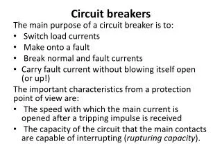
Fault Tolerance • Usually involves some form of redundancy • Hardware Fault-Tolerance • Memory and caches can be protected with ECC or parity • TMR is one of the most common forms of HW FT • Example of TMR (Triple Modular Redundancy) shown below
Fault Tolerance • Hardware Fault-Tolerance (cont’d) • Hardware devices can also be fabricated using processes that are less susceptible to radiation effects • Process of radiation hardening devices can be prohibitively expensive and time consuming • RadHard devices are generations behind their COTS counterparts in terms of performance and power consumption • Software Fault-Tolerance • Very cost-effective approach compared to hardware FT • Does not require any modification to device architecture • Leverages high-performance, low-power commercial off-the-shelf (COTS) components
Nicholas J. Wange, Justin Quek, Todd M. Rafacz, Sanjay J. Patel Univeristy of Illinois at Urbana-Champaign International Conference on Dependable Systems and Networks 2004 Characterizing the Effects of Transient Faults on a High Performance Processor Pipeline
Overview • Detailed Verilog model created for a microprocessor architecture, similar in complexity to the Alpha 21264 or AMD Athlon • Created a methodology for performing fault injection on a detailed latch-level simulation of a complex processor • Studied the propagation and/or masking of faults from the micro-architectural level to the architectural level
Verilog Processor Model Features • Alpha ISA subset • Speculative instruction scheduling • Memory dependence prediction • Sophisticated branch prediction • Up to 132 instructions can occupy the 12 stage pipeline
Fault-Injection Methodology • A time at which to inject fault is first selected • Randomly selected from 250-300 start points • Then the bit to corrupt is randomly selected • Injected faults are a single bit-flip of a state element • The trial is monitored for up to 10,000 cycles • At each cycle, architectural state is verified against non-injected golden execution • Trials are placed into four categories depending on the outcome • Each experiment consists of 25,000-30,000 trials
Trial Outcome Categories • Micro-architectural state match • Occurs when every bit of state in the machine is equivalent to a non-fault-injected simulation • Termination • Premature termination of the workload (execution error) • Silent data corruption • Trials that result in software-visible register or memory corruption (data error) • Gray area • Trial that does not result in failure (termination or silent data corruption) or micro-architectural state match
Results • This chart shows which types of state (relative to their contribution of overall state) contribute to silent data corruption and terminated results • Register file corruption is the leading cause of silent data corruption (data errors) and terminated (execution errors) outcomes
Results • Although noise is present in the graph, a correlation between processor utilization and benign fault rate can be seen • As the number of valid instructions (those that will commit results) in the pipeline decreases the benign fault rate increases • Benign faults do not affect program correctness
Shortfalls • Some instructions of the Alpha ISA were not implemented in the processor model • 10,000 cycle limit for monitoring is quite low • Certainly not enough time for most benchmarks to complete • Certain components were ignored for fault injection • These include caches and prediction structures • Corrupted registers were considered application failures • However, I have observed in my research that the majority of faults targeted at registers do not affect program execution or output • In my research I use the Simics cycle-accurate system simulation environment to perform fault injections into the register file of the Freescale P2020 dual-core PowerPC-based processor
Simics Simulation Fault-Injection Results • Simics simulation does not have the same level of detail needed to perform fault injection at the micro-architectural level, but does allow for register file fault-injection • The chart below shows results obtained when injecting single-bit faults into each of the general purpose registers, during a matrix multiplication application
Alex Shye, Joseph Blomstedt, Tipp Moseley, Vijay JanapaReddi, Daniel A. Connors IEEE Transaction on Dependable and Secure Computing April-June 2009 PLR: A Software Approach to Transient Fault Tolerance for Multicore Architectures
Process-Level Redundancy • Similar to TMR hardware fault-tolerance scheme • Creates a set of redundant processes for an application and compares each output to ensure correct execution • Leverages multiple processing cores by allowing the operating system to schedule redundant processes to available cores • Biggest challenge is maintaining determinism • Transparency can be achieved by maintaining user-expected process semantics • Does not require any modifications to target application, operating system, or device architecture • Important for legacy binaries whose source is no longer available
Sphere of Replication • Specifies the boundary for fault detection and containment • Data entering the SoR is replicated • All execution within the SoR is redundant • Any data leaving the SoR is compared to check for faults • Any execution outside the SoR is not protected • A typical hardware-centric SoR is shown on the left • PLR’s software-centric SoR is shown on the right
PLR Components • Monitor process • Maintains semantics • Figurehead process • Maintains semantics • Master process • Slave processes • Redundant processes • System call emulation • Maintains determinism • Responsible for fault detection and recovery
Maintaining Process Semantics • Example semantics: • Each application is assigned a process identifier (PID) which exists throughout execution and returned to the operating system after completion • When an application exits, it returns the correct exit code • A signal that is sent to a valid PID will have the intended effects (e.g. SIGKILL will kill the process) • Figurehead process • Original process becomes figurehead process after redundant processes are created • Does not perform any real work
Maintaining Process Semantics • Figurehead process (cont’d) • Sleeps and waits for redundant processes to complete • Receives application exit value and exits correctly • Responsible for forwarding incoming signals to all redundant processes • Monitor process • Certain signals are not easily forwarded • A SIGKILL signal would kill the figurehead process, but leave behind all redundant processes • Monitor process polls the state of figurehead process • If figurehead is killed or stopped, monitor process will kill or stop redundant processes
Maintaining Determinism & Transparency • System call emulation unit • Responsible for input replication, output comparison, and system call emulation • Responsible for ensuring that redundant processes interacting with the system appear as if only the original process is executing • System calls that return nondeterministic data (such as the system time) must be emulated to ensure all processes use the same data • Master vs. slave processes • System calls that modify any system state are only executed by the master process • Other system calls are performed once for the master process and replicated for the slave processes
Fault Detection • The system call emulation unit is responsible for providing fault detection and recovery • A fault causing the application to hang can be detected by a watchdog timer attached to the emulation unit • The timer begins when a processes enters the unit • If the rest of processes do not enter the unit within a specified amount of time, an execution error is signaled • Faults causing control-flow errors can also be detected if all processes do not request the same system call when entering the emulation unit
Fault Recovery • If an output mismatch occurs, a majority vote can be used to kill process producing incorrect data • Bad process is then replaced by forking correct process • A watchdog timeout can occur in two cases • If a faulty process calls the emulation unit while other processes are executing, it is killed and replaced by forking a correct process at the next system call • If a faulty process hangs while the other processes are waiting in the emulation unit, it is killed and replaced by a correct process • If a process fails, it is simply replaced by duplicating one of the remaining processes
Results • PLR eliminates all failed, abort, and incorrect cases • Output comparison converts abort and incorrect cases to mismatches • PLR detects failed cases, converting them into sighandler cases • A small number of failed cases are detected as mismatch with PLR • The mismatch is caught before the application can fail • Some floating-point benchmarks actually caused correct outcomes to become mismatches with PLR enabled • The specdiff tool included with the benchmarks uses a tolerance when checking output data, whereas PLR’s output comparison checks raw data
Overhead Incurred A) 2 processes B) 3 processes C) 2 processes optimized D) 3 processes optimized • Contention overhead is mainly caused by sharing memory bandwidth between redundant processes • Emulation overhead is caused by synchronization and transferring/comparing data in shared memory
Shortfalls • Functionality of system call emulation unit is detailed, however not many implementation details are provided • Replicating results would be hard to accomplish without more specific implementation details • Faults occurring during PLR code or operating system execution are not protected against • Only supports single-threaded applications • May not function as intended if using more redundant processes than physical cores available • Timeouts assume all processes are running concurrently
Conclusions • Simulation Fault-Injection • Allowed for injections to target areas not accessible to software or hardware fault-injection tools • Showed that many faults are masked before they are even visible to software • Process-Level Redundancy • Software fault-tolerance scheme • Similar to triple modular redundancy hardware scheme • Transparent to system and target application • Does not require any user intervention to apply protection • Able to detect all application failures and incorrect output