Download
1 / 41
440 likes | 727 Vues
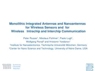
Monolithic Integrated Antennas and Nanoantennas for Wireless Sensors and for Wireless Intrachip and Interchip Communication. Peter Russer 1 , Nikolaus Fichtner 1 , Paolo Lugli 1 , Wolfgang Porod 2 and Hristomir Yordanov 1

E N D
MonolithicIntegratedAntennas and Nanoantennasfor Wireless Sensors and for Wireless Intrachip and Interchip Communication Peter Russer1, Nikolaus Fichtner1, Paolo Lugli1, Wolfgang Porod2 and Hristomir Yordanov1 1Institute forNanoelectronics, Technische Universität München, Germany 2Center forNano Science and Technology, University of Notre Dame, USA
Contents • Introduction • CMOS IntegratedAntennas • Nanoantennaswith MOM Tunnel Diodes • NanoantennasBased on CarbonNanotubes and Graphene • Alternative Materials and FabricationTechniques • Outlook
On-ChipNanoantennasforSensing and Communication • As thestructuresize of circuitdevices and componentsiscontinuouslydecreasingthesame will hold forantennas and radiationelementsused in integratedcircuitsforon-chip and chip-to-chipcommunication. • Followingthegeneralscalingtrendon-chipantennas will soonenterthemicrometer- and eventhenanometerregime.
Introduction • The rate of signal transmission on or between monolithic integrated circuits is limited by the cross-talk and the dispersion due to the wired interconnects. • An interesting option to overcome the bandwidth limitations is wireless chip-to-chip and on-chip interconnects via integrated antennas. • The electromagnetic coupling of antennas may occur via waves radiated into space and scattered by objects or via surface waves.
Contents • Introduction • CMOS IntegratedAntennas • Nanoantennaswith MOM Tunnel Diodes • NanoantennasBased on CarbonNanotubes and Graphene • Alternative Materials and FabricationTechniques • Outlook
On-chipmeanderantenna An intrachip wireless interconnect system using meander monopole on-chip antennas and operating at 22 GHz to 29 GHz is described in M. Sun, et al., “Performance of Intra-Chip wireless interconnect using On-Chip antennas and UWB radios,’’ IEEE Trans. on Ant. & Prop., vol. 57, no. 9, pp. 2756-2762, 2009. On-chip UWB radios in that frequency band are discussed there. The on-chip antennas arevmeander monopoles with 1 mm axial length.
CMOS IntegratedAntennas Schematicdrawing of a chipwith an integratedantenna • Instead of dedicating chip area for the antenna the antenna can make use of the available on-chip metallization. • This can be obtained by dividing the top metallization layer into patches and impressing an RF signal across the gap between the patches.
Differential Lines, Connecting the Digital Circuits Under the Separate Antenna Patches
CMOS IntegratedAntennas 1.1 mm 2 mm 50 mm Simulatedcurrentdistribution of a two-patchantennaoperated at 66 GHz
CMOS IntegratedAntennas Photograph of the open slot antenna H. Yordanov and P. Russer, “Area-efficient integrated antennas for inter-chip communication,” Proc. of the 40th European Microwave Conference, EuMC 2010, Paris, France, Sep 2010.
CMOS IntegratedAntennas Main Direction Minimum Direction
Contents • Introduction • CMOS IntegratedAntennas • Nanoantennaswith MOM Tunnel Diodes • NanoantennasBased on CarbonNanotubes and Graphene • Alternative Materials and FabricationTechniques • Outlook
Integration of Antennaswith MOM Diodes • A promising novel concept for infrared (IR) detectors is the combination of a nanoantenna with a rectifying element. • The rectifying element extracts a DC component from the rapidly-varying current delivered from the nanoantenna. Semiconductor diodes are widely used, but they encounter frequency limitations for the mm-wave and long-wave IR regime. • It has been demonstrated that MOM tunnel diodes can provide rectification for IR and even optical radiation
AntennawithIntegrated MOM Diode The MOM dieodeisnaturalyformed at theoverlapareabetweentheantennaarms P. Esfandiari, G. Bernstein, P. Fay, W. Porodet al., “Tunableantennacoupled metal-oxide-metal (MOM) uncooled IR detector,” in Proc. of SPIE, vol. 5783, 2005, pp. 471 – 482.
ACMOMD Design MOM diode Al-AlOx-Pt Design 1 Shadow evaporation diode formed antenna antenna Al Pt MOM diode Al-AlOx-Pt Design 2 Two step lithography Al Pt Electrical leads
linearly polarized IR radiation Metal X Oxide Metal X Al-AlOx-Al nanoantenna Electrode 1 Electrode 2 Metal Oxide Metal Metal Oxide Metal Symmetric MOM - Unbiased QM Tunneling For symmetrical barrier MOM No net e-transfer over complete cycle of IR radiation No net QM Tunneling current Net e-transfer for one half cycle Electrode 1 Electrode 2 Net e-transfer for other half cycle Electrode 1 Electrode 2
Metal X Metal X Electrode 1 Electrode 2 +applied biased Biased symmetric MOM diode Symmetric MOM - Biased Symmetric MOM - Biased linearly polarized IR radiation Al-AlOx-Al nanoantenna Electrode 1 Electrode 2 Electrode 1 Electrode 2 For BIASEDsymmetrical barrier MOM Net e-transfer over complete cycle of IR radiation
Asymmetric MOM linearly polarized IR radiation Vacuum level Δ W1 1 2 Al-AlOx-Pt nanoantenna Metal X Metal Y Electrode 1 Electrode 2 Equilibrium condition Δ = 1 2=W1-W2 Metal X Oxide Metal Y Metal X Metal Y Electrode 1 Electrode 2 Asymmetric MOM - Unbiased W2 For unbiased asymmetrical barrier MOM Net e-transfer over complete cycle of IR radiation Metal X Metal Y Electrode 1 Electrode 2
Al-AlOx-Pt Overlap 50x80 nm Al Pt Two Step Lithography Devices OpticalMicroscope Images 20 finished devices through 2 step lithography process 2-step lithography dipole antenna Corresponding SEM image Gold bonding pads
SEM Image of a Shadow Evaporation Device J. A. Bean, B. Tiwari, G. H. Bernstein, P. Fay, and W. Porod, “Thermal infrareddetectionusingdipoleantenna-coupledmetal-oxide-metaldiodes,” Journal of Vacuum Science & Technology B: Microelectronics and Nanometer Structures, vol. 27, p. 11, 2009.
One Step Lithography Devices MOM overlap area of a Shadow evaporation device
Contents • Introduction • CMOS IntegratedAntennas • Nanoantennaswith MOM Tunnel Diodes • NanoantennasBased on CarbonNanotubes and Graphene • Alternative Materials and FabricationTechniques • Outlook
CarbonNanotubeAntennas • A further considerable size reduction of integrated antenna structures may be achieved using CNTs. • CNTs exhibit exceptional electron transport properties, yielding ballistic carrier transport at room temperature with a mean free path of around 0.7 mm and a carrier mobility of 10,000 cm2/Vs.
CarbonNanotubeAntennas • Quantum transport effects in the CNT yield a quantum capacitance CQand a kinetic inductanceLKin addition to the geometric capacitance CGand inductance LG. • The phase velocity for the modified equivalent circuit is around 0.02 c0which is in accordance with the reduced wavelength of the surface plasmons.
CarbonNanotubeAntennas • Due to the extremely high aspect ratio (length to cross sectional area), CNTs have AC resistances per unit length in the order of several kW/μm. • This causes high conduction losses and thus seriously decreases the efficiency and the achievable gain ofnanoantennas. • This problem could be bypassed using of arrays of nanoantennas or a bundle of parallel nanowires.
GrapheneAntennas • LikeCNTs, graphene also exhibitsexcellentconductivity and slowwaveproperties. Theachievableslow-waveeffect in plasmonmodesis in the order of c0/100. • At THzfrequencies a populationinversion in thegraphenelayercanberealizedbyopticalpumpingorforwardbiaswhichyields an amplification of thesurfaceplasmon. • Grapheneallowstherealization of planarstructures and also therealization of activecircuits. J. Moon et al., “DevelopmenttowardWafer-Scalegraphene RF electronics,” in Topical Meeting on Silicon MonolithicIntegratedCircuits in RF Systems, January 11–13, 2010, New Orleans, LA, Jan 2010, pp. 1-3.
GrapheneAntennas Theoretical investigations have shown that antennas with sizes in the order of several hundred nanometers are suitable to radiate electromagnetic waves in the terahertz band, i. e. from 0.1 THz to 1 THz. J. M. Jornet and I. F. Akyildiz, “Graphene-based nano-antennas for electromagnetic nanocommunications in the terahertz band,” in Proc. of 4th European Conference on Antennas and Propagation, EUCAP, 2010.
Contents • Introduction • CMOS IntegratedAntennas • Nanoantennaswith MOM Tunnel Diodes • NanoantennasBased on CarbonNanotubes and Graphene • Alternative Materials and FabricationTechniques • Outlook
Alternative Materials and FabricationTechniques • The antennas described previously are generally fabricated with conventional technologies, namely evaporation of the metallic films followed by patterning via photo or electron-lithography. • In the CNT or graphene case, the conductive layers have to be grown epitaxially on the given substrate. • Especially when small dimensions are required, as for the nanometer gaps required in plasmonic structures or in nanometer scale MOM diodes, a very interesting alternative could be offered by nanotransfer techniques.
Schematic of Direct Metal-Transfer A metal coated high resolution heterostructure is pressed onto a substrate, thereby creating nanometer separated electrodes. • S. Harrer, S. Strobel, G. Scarpa, G. Abstreiter, M. Tornow, and P. Lugli, “Room temperature nanoimprint lithography using molds fabricated by molecular beam epitaxy,” IEEE Trans. Nanotechnology, vol. 7, no. 3, pp. 363–370, 2008. • S. Harrer, S. Strobel, G. Penso Blanco, G. Scarpa, G. Abstreiter, M. Tornow, and P. Lugli, “Technology assessment of a novel highyield lithographic technique for sub-15-nm direct nanotransfer printing of nanogap electrodes,” IEEE Trans. Nanotechnology, vol. 8, no. 6, pp. 662 –670, 2009.
Transfer Metal Padswith a Gap of a Few Nanometers. • Transferred metal pads, exhibiting a gap featuring line separations down to approximately 9 nm. • The structures could be transferred along the complete length of the mold (approximately 4 mm) with an efficiency of about 80%. • Structures containing several lines separated by nanometer gaps have also been realized.
Contents • Introduction • CMOS IntegratedAntennas • Nanoantennaswith MOM Tunnel Diodes • NanoantennasBased on CarbonNanotubes and Graphene • Alternative Materials and FabricationTechniques • Outlook
Conclusion and Outlook • As the structure size of circuit devices and components is continuously decreasing the same will hold for antennas and radiation elements used in integrated circuits for on-chip and chip-to-chip communication. • Following the general scaling trend,on-chip antennas will soon enter the m- and even the nanometer regime. • Integrated antennas based on nanoelectronics provide a tremendous potential for the realization of novel devices and systems from DC up to the optical range. • The applications will cover wireless intra-chip and interchip transmission at Gbit/s rates, field sensors and photon harvesting systems.
Conclusion and Outlook • Intrachip and interchip wireless broadband communication at millimeterwave carrier frequencies can be realized in CMOS technology and will allow the transfer of Gbit/s data rates. • A further size reduction of antenna structures will be possible by integration of CNT and graphene antenna structures. • When small dimensions are required, as for the nanometer gaps required in plasmonic structures or in nanometer scale MOM diodes, a very interesting alternative could be offered by nanotransfer techniques.