Mechanics Analysis of Rolling Process
Understand the principles of rolling process mechanics, defects, and design for manufacturing. Analyze torque, power, productivity, and process variations. Learn about friction force, true strain, and power requirements for effective metal forming.

Mechanics Analysis of Rolling Process
E N D
Presentation Transcript
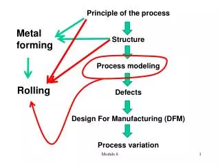
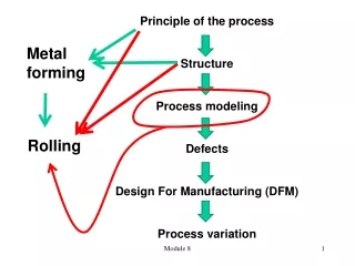
Principle of the process Structure Process modeling Defects Design For Manufacturing (DFM) Process variation Metal forming Rolling Module 8
Rolling Process: Mechanics Analysis • Two opposite rolls and a piece of material flows between them. The shape of rolls can be designed in a different form to construct a product with different cross sections. handout 8 b
System parameters Operating parameters Objectives of mechanics analysis • Physical phenomenon • Torque • Power • Productivity Product parameter handout 8 b
w t L Physical phenomenon Spreading: mass conservation (volume before rolling = volume after rolling) Volume flow rate conservation • Product parameter (t0, tf) cannot be changed, and they need to be achieved through the process. • In the process, w, L, and vf are derived parameters. • Vf represents the productivity, while w and L are product parameters. handout 8 b
Vo < Vr < Vf No-slip point Slipping Slipping Work velocity = Roll velocity Production rate handout 8 b
For the rolling process, the true strain is: The average flow stress is the same expression, i.e. e n k = Y f + 1 n handout 8 b
It is the friction between the work and the roll that drives the workflow between two rolls. Greater Friction Force Lesser Friction Force No-slip point The friction force is developed based on • coefficient of the friction and • compression force of rolls handout 8 b
Max. Possible Draft Radius of the roll Friction coefficient Friction causes Rolling If Friction=0, then draft=0, means NO ROLLING Condition to roll- Coefficient of the friction draft, d = |tf-t0|: dmax handout 8 b
Condition to roll- Power to drive the roll and work piece Roll Force (F) Integrating “unit roll pressure” over roll work “contact area” • The pressure varies along the contact length. • F is assumed to be at the middle of the L. • W is the width of the roll. handout 8 b
Torque Contact length d Contact force N: rotation speed of the roll, rev / min Power Power is a function of d. Increase of d leads to increase of P handout 8 b
Condition to roll- Power to drive the roll and work piece When the required power (d) is greater than the supplied power, the rolling of a work piece with d is not possible. Therefore, the required power = supplied power will lead to a critical draft d or maximum d. Criterion 1: Criterion 2: required power = supplied power The actual maximum draft for a rolling system is the smaller one computed from the two criterions above.
Example: A 10-in. –wide, 1.0-in – thick plate is to be reduced in a single pass in a two-high rolling mill to a thickness of 0.8 in. The roll has a radius = 20 in., and its speed = 50 ft/min. The work material has a strength coefficient = 35.000 lb/in.2 and a strain hardening exponent = 0.2. Determine (a) roll force, (b) roll torque, and (c) power required to accomplish this operation. handout 8 b
Given: rolling, t0=1.0 in., tf=0.80 in., w=10.0 in., R=20 in., vr=50 ft/min, flow curve n=0.20 and K=35,000 lb/in2. Find: (a) F, (b) T, (c) HP. Draft d=1.0-0.8=0.2 in. Contact length L = (20×0.20)0.5 = 2.0 in. True strain ε = ln (1.0/0.8) = ln 1.25= 0.223 Average flow stress f = 35,000(0.223)0.20/1.20 = 21,607 lb/in2 Rolling force F = 21,607(10)(2) = 423,149 lb handout 8 b
Torque T = 0.5(432,149)(2.0) = 432,149 in-lb. L: contact length Unit of R is converted from in to ft N = (50 ft/min)/(2π×20/12) = 4.77 rev/min. Perimeter 12,951,849 Power P=2 π (4.77)(432,149)(2) = 25,929,940 in-lb/min HP = (12951849 in-lb/min)/(396,00) = 134.9 hp handout 8 b