Download
1 / 29
290 likes | 394 Vues
The CLIC Test Facility (CTF3) continues to demonstrate significant advancements in RF power source generation and beam stability for particle acceleration. This report details the successful phase coding techniques applied to drive beam generation, results from two-beam acceleration studies, and improvements in current stability achieved after the delay loop implementation. The use of photoinjectors, RF deflectors, and combined beam studies have paved the way for enhanced performance, achieving peak RF power of 170 MW and near-nominal CLIC power of 135 MW. Continuous optimization and collaboration across 35 institutes highlight ongoing research and development efforts.

E N D
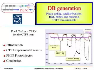
DB generation Phase coding, satellite bunches, R&D results and planning, CTF3 measurements Current from Linac • Introduction • CTF3 experimental results • PHIN Photoinjector • Conclusion Current after Delay Loop Current in the ring
TL1 Laser CLEX CTF 3 – CLIC Test Facility demonstrate CLIC RF power source Drive Beam generation (fully loaded acceleration, bunch frequency multiplication 8x) Test CLIC accelerating structures Test power production structures (PETS)aaaa. Delay Loop42m Combiner Ring – 84m RF deflector Injector Linac 3.5A – 1.2µs150 MeV Test Beam Line - TBL 28A140ns150 MeV TL2 Califes TBTS TBL Two Beam Test Stand - TBTS Probe Beam - CALIFES
recombinationx 4 recombination x 2 bunch lengthcontrol bunchcompression fully loadedacceleration structures12 GHz phase-coding PETSon-off Decelerationstability two-beamacceleration structures 30 GHz CTF3 base line programme CTF3 – R&D Issues - where R1.1 – structuresR1.2 – DB generation R1.3 – PETS on-offR 2.1 – structure materialsR 2.2 – DB deceleratorR 2.3 – CLIC sub-unit R.Corsini
TBTS – Two beam test stand • Combined beam of Combiner Ring extracted(up to 15A/28A), transported to CLEXused for power production in TBTS and TBL • TBTS: Line for Two-beam acceleration studies • both Drive Beam and Probe Beam to the end • Optics and first breakdown kick measurements • 170 MW (peak) RF power reached inPETS power production structuretotal pulse length ~200 ns • => reached nominal CLIC power (135 MW) • acceleration structure is being installed now
TBL - Test Beam Line / Califes • TBL: Line for deceleration studies • Installation of beam line with all magnetsand BPMsfinished, 1st PETS prototypeinstalled (several more this year) • Beam transported to the end • 10A beam generated 20 MW RFpower in the PETS structure, follows expectation Califes: Probe beam photo-injector Laser performs well, nominal bunch charge reached, accelerated to 140 MeV Beam transported to the end with ~100% transmission, reliable beam to TBTS Detailed optics studies CTF3/CLIC collaboration: increased to 35 institutes
RF pulse at structure input MKS05 MKS03 MKS06 MKS07 1.5 µs beam pulse RF pulse at structure output Spectrometer 4 Spectrometer 10 analog signal Full beam-loading acceleration in CTF3 • high current routine operation demonstrated Measured RF-to-beam efficiency 95.3% Theory 96%(~ 4 % ohmic losses)
Beam current stability • operation sensitive to beam current variations • current stability ~ 0.15% end-of-linac, ~ 0.16% combiner ring • current variation over the pulse, also due to SHB phase switch=> different energy • => feed-forward will be implemented this run badlyphasedSHB
RF / Beam energy stability • RF phase stabilisation for klystrons put into operation=> slow phase variation down to ~ 0.5 degree • phase jitter ~ 0.1 – 0.2 degree (after compression) • short term energy jitter from RF presently measured ~ 0.6 10-3 • slow power variation (from RF pulse compression) several %=> temperature feed-back will be implemented this run σ Total RF power
TL1 2005 2004 SHB DL SHB CR gun TL2 CLEX SHB buncher 2 accelerating structures Delay Loop operation • 1.5 GHz sub-harm.bunching system • 1.5 GHz RF deflector
SHB system – Phase coding Key parameters for the SHB system: 1) time for phase switch < 10 ns (15 1.5 GHz periods) 2) satellite bunch population < 7 % (particles captured in 3 GHz RF buckets) satellite bunch population: phase switch: main bunch satellite bunch Satellite bunch population was estimated to ~8 %. Phase switch is done within eight 1.5 GHz periods (<6 ns).
DL 7A Delay loop status • factor 2 combination re-established after 2 years • current about doubled, up to ~7 A (~0.5 A in satellites) CR Current in the Delay Loop Current after Delay Loop Current from Linac
injection line 1st turn 2nd septum 1st deflector 2nd deflector local inner orbits lo RF deflector field 4rd 3rd lo/4 RF injection in combiner ring combination factors up to 5 reachable in a ring Cring = (n + ¼) l
Combination setup procedure • Developed a setup procedure to optimize combination • 5 parameters • Amplitude and phase in each deflector • Ring path length (wiggler for path length tuning) • Monitor trajectory differences over various turns s
Isochronicity Tuning • ring optics needs to be isochronous to keep short bunch length=> high power extraction efficiency • Streak Camera observations non-isochronous – 2nd turn isochronous – 60th turn momentum compactionαp < 10-4
CR RF deflectors =>Instability RF deflectors had a vertical mode that deflected the beam Could be minimized by proper phase advance – not done effect perfectly understood, reproduced in simulation => not an issue current vertical horizontal BPM signals shoving vertical instability Old deflectors, undamped New deflectors, damped damping loads BPM signals, no instability
15 A Combiner ring status routinely factor 4 combination achieved with 15 A, 280 ns (withoutDL) CR 280 ns 280 ns Current from Linac 1st turn of 1st pulse 2nd turn of 1st pulse and 1st turn of 2nd pulse 3rd turn of 1st pulse,2nd turn of 2nd pulse, 1st turn of 3rd pulse Current in the ring All 4 pulses
DL 30A Factor 8 combination (DL+CR) • ~28 A combined achieved, nominal 140 ns pulse CR Current from Linac Current after Delay Loop Current in the ring
Factor 8 combination (DL+CR) Current from Linac Current after Delay Loop Current in the ring
Recombination studies • emittance measurement (vertical plane)combined 4x beam < 150 π mm mrad • streak camera measurements Turn 1 Turn 2 • orbit closure well controlled • combination to be optimized • dispersion/isochronicity 666 ps initial bunch spacing Turn 3 from DL Turn 4 83 ps final bunch spacing
Adjustment of the path length Wiggler behaviour as expected CR: ~1.5 mm difference only control to better than 0.5 mm • DL: correct length accessible => CF 5, - 1/5 lRF About 1.5 mm Expected ring length for nominal wiggler current Measured Lfrac = - 1/CF lRF CF 4, - 1/4 lRF
State of the art today • ongoing Drive Beam generation demonstration in CTF3. • Full beam loading (95% transfer), high current (up to 5A) in DBA • Sub-Harmonic bunching, phase coding (7% satellites) • Bunch train recombination factor 2 in Delay Loop (up to ~7 A) • Bunch train recombination factor 4 in Combiner Ring (3.8 to 15 A) • Recombination 2x4 DL/CR achieved ~ 28 A • Isochronous operation of ring, ap < 10-4 • Transverse rmsemittance 100 π mm mrad (end of linac only)150 π mm mrad (vert., 4x combination) • Bunch length control to < 1 mm rms (end of linac only) • Control of ring length to better than 0.5 mm • Beam current stability ~ 0.15% end-of-linac, ~0.16% combiner ring
To be addressed … • Dispersion / isochronicity in DL/CR • Full bunch length manipulations in TL2 after combination(we see from RF that the form factor is close to 1) • full beam (28 A) to users (new TL2/CLEX BPM readout) • RF power production in CLEX • Two-beam operation in TBTS (relevant CLIC sub-unit)(we started with CCC operator supervision) • Deceleration stability • Loss management, machine protection system • Satellite bunches • Photo injector option • …
PHIN Photo-injector • Smaller transverse emittance, shorter bunches, no energy tails, no satellites • Bunch charge lower than present injectorshown up to 2.5 nC, above nominal!, also 2.3 nC for long train reached • Beam energy ~ 5-6 MeV • Emittance measured ~7 π mm mrad • Very good agreement with simulations • started to measure laser/beam stability:better than requirements E-beamsize: x=1.53mm Lasersize: x=0.74mm δ=0.35mm δ=0.15mm
Laser system status • setup significantly improved (beam path, optical crystal,…) • For PHIN all laser main target parameters fulfilled !!! • 0.8% beam current stability (without feedback on the laser) • long term studies (cathode response, …) to be done • Laser phase coding to be demonstrated this year • Booster amplifier needed (~ June)
Conclusion • Drive Beam generation very well covered • fully loaded operation demonstrated and routinely used • full bunch train combination2x4shown (DL+CR) • optimization procedures developed • started to address performance and stability • next major steps: • two beam tests in TBTS • drive beam deceleration in TBL • CTF3 experimental program + plans for 2010=> see Roberto’s talk • Many THANKS to all collaborators!
2009 CTF3 experimental program Goals • 30 GHz:One structure test (TM02) +breakdown studies • PHINBeam characterization, reach ½ of nominal bunch charge • CALIFESBeam characterization, beam to TBTS (most likely still reduced current) • Delay LoopBack in operation, retrieve combination x 2 (~ 7 A) • Combiner RingFinal optics checks, isochronicity, put together with DL (> 24 A) • TL2Complete commissioning (tail clipper), bunch length control, > 20 Ato users • TBTSPETS to nominal power/pulse length (15 A, recirculation) • Beam commissioning of probe beam line • First accelerating structure tests (one structure ? – CLIC G) • Two-beam studies (deceleration/acceleration), initial breakdown kicks studies • TBLPETS validation (100 MW, need > 20 A), beam line studies (2-3 PETS ?) • OthersCDR studies in CRM, beam dynamics benchmarking, stability studies, control of beam losses…