Insight into Arithmometer Mechanics: From Number Input to Output Gears
80 likes | 102 Vues
Explore the intricate workings of Thomas de Colmar’s Arithmometer through a breakdown of mechanisms like Number Selectors, Step Gears, and Carry Tooth, enhancing your understanding of this historical device.

Insight into Arithmometer Mechanics: From Number Input to Output Gears
E N D
Presentation Transcript
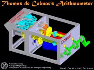
Thomas de Colmar’s Arithmometer Bits On Our Mind 2005, Tim Kostka
Number Selectors – Input Number Number Selectors These gears indicate the input number. They are able to slide up and down through the 0-9 positions. Here, the input number is 37.
Number Wheels – Output Number Number Wheels The position of the number wheels indicate the output number. On the actual device, only one number would be visible—in the model, the frame is left open for visibility. Here, the output number is 42.
Power Transmission Step Gears Power Axle The power axle transfers power to the step gears. It also keeps them in sync by turning them all at the same time and through the same axis.
Step Gear Mechanism Step Gear Number Selector Due to the design of the step gear, these two mating gears have a variable ratio. Depending upon the input number, the step gear causes the number wheel to rotate up to 9 places. This is varied by sliding the mating gear to the appropriate position.
Carry Mechanism Trigger Disengaged Position Engaged Position When the number wheel moves from 9 to 0, the carry mechanism is triggered. A small protrusion on the bottom of the number wheel pushes the top carry slider into its engaged position. Although the is not much motion, it is enough to engage the carry tooth seen on the next slide.
Carry Tooth Mechanism Disengaged Position Engaged Position When the carry mechanism is triggered, the carry tooth (blue) is lined up with the mating gear (yellow). When engaged, this advances the number wheel by one digit.
Locking Mechanism for Reliability Locking Mechanism The locking mechanism is provided for reliability. It prevents the number wheel from rotating between turns of the wheel. Here, it is in the locked position. When the step gear rotates enough, it will disengage.