Download
1 / 31
310 likes | 463 Vues
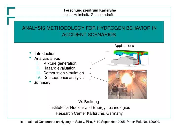
Forschungszentrum Karlsruhe in der Helmholtz-Gemeinschaft. ANALYSIS METHODOLOGY FOR HYDROGEN BEHAVIOR IN ACCIDENT SCENARIOS. Applications. Introduction Analysis steps Mixture generation Hazard evaluation Combustion simulation Consequence analysis Summary. W. Breitung

E N D
Forschungszentrum Karlsruhein der Helmholtz-Gemeinschaft ANALYSIS METHODOLOGY FOR HYDROGEN BEHAVIOR IN ACCIDENT SCENARIOS Applications • Introduction • Analysis steps • Mixture generation • Hazard evaluation • Combustion simulation • Consequence analysis • Summary W. Breitung Institute for Nuclear and Energy Technologies Research Center Karlsruhe, Germany International Conference on Hydrogen Safety, Pisa, 8-10 September 2005. Paper Ref. No. 120009.
OBJECTIVES • The outcomeof a hydrogen related accident depends on many parameters and complex • physics • Need to develop a mechanistic understanding and complete modelling procedure • - to predict accident progress and consequences • - to develop efficient mitigation measures • - to support development of safe hydrogen technologies • - to provide reliable data base for rules, codes and standards • Paper describes approach and current status of FZK analysis methodology
COMBUSTIBLE CRITERIA FOR COMBUSTION COMBUSTION CONSEQUENCE MIXTURE HAZARD SIMULATION SIMULATION ANALYSIS GENERATION POTENTIAL Problem geometry Flammability y Mechanical and Slow Slow deflagration deflagration Mitigation Flame acceleration thermal loads FLAME3D FLAME3D y Scenario Structural response Detonation- transition Fast turbulent Fast turbulent SDO ABAQUS deflagration deflagration COM3D COM3D Sources y Human Detonation Detonation Distribution effects DET3D DET3D GASFLOW GP Program ANALYSIS METHODOLOGY • FZK develops numerical codes and methods for consistent analysis of hydrogen behavior in • accident scenarios, four main steps: • More than 150 person-years of experience
I. MIXTURE GENERATION • Scenario:Release of cold GH2 (22K) from LH2-tank at bottom of vehicle, parked in garage • Sources: 1 W energy deposition, 170 g GH2/d, assume 5 x 34 g H2 releases • What is effect of release rate on risk? COMBUSTIBLE MIXTURE GENERATION Problem geometry Mitigation Scenario Case1: 3,4 g H2/s for 10 s Sources Distribution GASFLOW cloud 4% hydrogen
MIXTURE GENERATION : Case 2 • GH2 source of 0,34 g H2/s for 100s duration cloud 4% hydrogen
II. HAZARD POTENTIAL • What hazard is actually presented by the calculated H2-air distribution ? • Hydrogen hazard is mainly determined by the • fastest possible combustion regime of the • mixture • slow deflagration • fast turbulent deflagration • detonation • Transition criteria were developed to estimate • conservative (fastest) combustion regime • possible for a given H2-air mixture and geometry • inert /slow • slow/fast • deflagration/detonation CRITERIA FOR CRITERIA FOR HAZARD HAZARD POTENTIAL POTENTIAL Flammability Flammability y y Flame Flame acceleration acceleration y y Detonation- transition - Detonation on set y y GP - Program
0.8 p = 0.1 MPa 0 0.7 T = 400 K 0 0.6 D = 1m 0.5 D = 5m Volume fraction hydrogen 0.4 0.3 DDT limit 0.2 Flame acceleration limit 0.1 Flammability limit 0.0 0.0 0.1 0.2 0.3 0.4 0.5 0.6 Volume fraction steam GP-CODE • All criteria implemented in interactive • GP-code, are function of • p0, T0, xH2, xO2, xH2O, xN2,D • Example for H2-air-steam mixtures • mixtures above 60 vol% are inert • flammability and flame acceleration • limits nearly coincide on the rich side • the DDT limit is scale dependent, • in larger system (D) wider range of • mixtures can undergo a deflagration- • to-detonation transition
HAZARD EVALUATION FOR GARAGE EXAMPLE 3.4 g H2/s, 10s 0.34 g H2/s, 100s • Criteria are evaluated on-line in • GASFLOW from known H2-distribution • CASE 1: • significant and stable volume of • combustible mixture • potential for flame acceleration and • DDT exists during and shortly after • release • CASE 2: • only small volume is able to support • deflagrations, disappears shortly • after end of release • no DDT hazard • inherent mixing mechanisms sufficient • to dilute source • H2 release in confined spaces tolerable up • to certain critical rate (here approx. 0.3 g/s), • larger rates require additional measures for • hazard control
III. COMBUSTION SIMULATION COMBUSTION COMBUSTION • Different physics involved in different combustion modes • Three CFD codes under development and in use at FZK • Codes model stable combustion regimes, transition phenomena • covered by criteria SIMULATION SIMULATION Slow Slow deflagration deflagration FLAME3D FLAME3D Fast turbulent Fast turbulent tion deflagra deflagration COM3D COM3D Detonation Detonation DET3D DET3D
COMBUSTIBLE MIXTURE GENERATION Plant geometry Mitigation Scenario Sources Distribution GASFLOW CRITERIA FOR CRITERIA FOR HAZARD HAZARD POTENTIAL POTENTIAL Flammability Flammability y y Flame Flame acceleration acceleration y y Detonation Detonation on on - - set set y y GP - Program CONSEQUENCE ANALYSIS Mechanical and thermal loads Structural response ABAQUS Human effects LOCAL EXPLOSION IN CONFINED VOLUME • Test chamber at FZK for hydrogen • release and local explosion experiments • in confined spaces under controlled flow • conditions • volume 160 m3 • air ventilation up to 24,000 m3/h • Structural stability against dynamic pressure • loads tested under conservative conditions • stoichiometric, homogeneous mixture • locally concentrated in cube (2-16g H2) • obstacles in cubes to reach high flame • speeds Air supply Duct work Test chamber COMBUSTION COMBUSTION SIMULATION SIMULATION Slow Slow deflagration deflagration FLAME3D FLAME3D Fast turbulent Fast turbulent deflagration deflagra COM3D COM3D Detonation Detonation DET3D DET3D Lower compartment
COM3D SIMULATION FOR FZK TEST CHAMBER • Numerical simulation • Fast local turbulent H2 - air • deflagration in FZK test • chamber • 8 g H2 • p0 = 0.1 MPa • xH2 = 29.8 vol%
Sensor 16 wall, far Sensor 20 wall, near Sensor 14 floor Sensor 6 upper corner IV. CONSEQUENCE ANALYSIS • Output of CFD combustion calculation allows estimate of consequences CONSEQUENCE ANALYSIS Mechanical and thermal loads Structural response SDO ABAQUS Human effects • Example: Pressure loads of 8g H2 test in FZK facility
STRUCTURAL RESPONSE: Test chamber • Response of FZK test chamber simulated with ABAQUS • - input : p(t) at 8000 locations from COM3D • - output: stress and strain in test chamber components • Maximum displacement in frame (mm) • Maximum stress in inner wall (MPa) • Results: Walls and framework structure can confine tested fast local combustions, • limiting hydrogen mass for test chamber estimated with model
Dp+ I+ 106 t Unconfined gaseous detonations 16g H2 2g H2 105 Partial demolition 50%-75% of walls destroyed FZK experiments 16g H2 Positive overpressure Dp+ [Pa] Major structural damage, some wrenched load bearing members fails 2g H2 104 Minor structural damage wrenched joints and partitions glass breakage 103 100 101 102 103 104 Positive impulse I+ [Pa*s] • p-i data from W.E. Baker et al • Gaseous detonation data from Dorofeev et al STRUCTURAL RESPONSE: Damage thresholds for civil buildings • Comparison of measured blast wave parameters in FZK test chamber to known damage • limits of civil buildings.
Dp+ I+ t T+=2I+/Dp+ 106 Unconfined gaseous detonations 16g H2 Lung rupture T+ 2g H2 NASA 50% ear drum rupture 105 16g H2 FZK experiments Lethality from whole body impact (60 kg body weight) ear drum rupture Positive overpressure Dp+ [Pa] 2g H2 Skull fracture (60 kg body weight) 104 Temporary ear threshold shift 103 • Threshold data converted • from W.E. Baker et al • - Gaseous detonation data • from S.B. Dorofeev et al 10-4 10-3 10-2 10-1 100 101 Positive impulse duration T+ [s] HUMAN EFFECTS: Injury thresholds • Comparison of measured blast wave parameters Dp+ and T+ in FZK test chamber to • known injury thresholds
SUMMARY • A mechanistic analysis procedure for hydrogen behavior in accidents was developed, • the methodology is based on 3d CFD tools, it addresses four main steps: • combustible mixture generation • hazard evaluation • combustion simulation • consequence analysis • Two examples for hydrogen behavior in confined spaces were presented: • - hydrogen release is safe up to a critical release rate, which depends on • problem details and which can be evaluated with 3D simulations • blast effects from local explosion of 2 - 16 g of GH2 can cause • a) only minor damage to normal civil buildings (glass breakage, joints, ...), • b) ear damage, more serious injuries appear unlikely (lung rupture, …)
Forschungszentrum Karlsruhein der Helmholtz-Gemeinschaft Thank you for your attention on behalf of the whole team Dr. M. Kuznetsov, IKET Dr. A. Lelyakin, IKET Dr. G. Necker, ProScience Dr. R. Redlinger, IKET Dr. P. Royl, IKET DI (FH). K. Sempert, ProScience Dr. J. Starflinger, IKET Dr. S. Stober, IKET DI (FH). G.Stern, ProScience Dr. J.R. Travis, Ing.Büro DPT Fr. DI. A. Veser, ProScience DI. J. Yanez, IKET Dr. A. Denkevits, IKET DI. J. Grune, Pro Science Dr. A. Friedrich, ProScience Dr. T.Jordan, IKET Fr. B. Kaup, IKET Dr. A.Kotchourko, IKET
HYDROGEN RELATED ACCIDENTS : What happens? Person damage Combustion regimes Effect of geometry 100 70 90 2,5 injuries 60 80 deaths 2 50 70 GH2 60 40 1,5 % of incidents affected persons per incident 50 % of incidents 30 40 1 30 20 20 0,5 10 10 0 0 0 no release to environm.. release with slow defl.. release with fast defl.. no release, reaction in system partiall or fully conf. release release w/o ign. no ignition slow defl. fast defl. open environ. detonat. 100 70 2,5 90 60 80 2 70 50 60 LH2 40 1,5 affected persons per incident 50 % of incidents % of incidents 30 40 1 30 20 20 0,5 10 10 0 0 0 consequences vary significantly degree of confinement is important full spectrum of flame speeds observed Kreiser et al, IKE 2-116, Univ. Stuttgart, 1994
air outlet air inlet 100 ppm H2 4% H2 (LEL) GENERAL ACCIDENT PHASES Whats new about hydrogen ? mixing with air ignition laminar deflagration fast turb. deflagration detonation gas release
SAFETY RELEVANT PROPERTIES • Hydrocarbons show similar • property profiles • The property differences to • hydrogen reach almost a • factor 10 in each of the • accident phases Hydrogen specific safety investigations are needed
1,5 • Safety relevant properties of • hydrogen • - natural gas dry • - propane • - gasoline vapour 5 density 1,0 buoyancy 0,5 4 0,0 140 specific combustion heat 3 -0,5 3 120 kg/m -1,0 rair-r gas(kg/m3) 2 100 -1,5 -2,0 80 MJ/kg 1 -2,5 60 -3,0 Wasserstoff Erdgas trock. Propan Benzindampf 0 40 hydrogen natural gas dry propane gasoline vapour -3,5 20 0 0,7 80 0,35 diffusioncoefficient hydrogen natural gas dry propane gasoline vapour ignition energy flammability limit 0,6 70 0,3 F=1 60 0,5 0,25 50 0,4 /s 0,2 2 mJ UEL-LEL (%) 40 cm 0,3 0,15 30 0,2 0,1 20 0,1 0,05 10 0 0 0 hydrogen natural gas dry propane gasoline vapour hydrogen natural gas dry propane gasoline vapour hydrogen natural gas dry propane gasoline vapour 0,12 3 detonation- sensitivity l-1 laminar flame velocity 0,1 2,5 F=1 F=1 0,08 2 1/mm 0,06 m/s 1,5 0,04 1 0,02 0,5 0 0 hydrogen natural gas dry propane gasoline vapour hydrogen natural gas dry propane gasoline vapour SAFETY RELEVANT PROPERTIES: ANOTHER VIEW
COMBUSTIBLE MIXTURE GENERATION Plant geometry Mitigation Scenario Sources Distribution GASFLOW CRITERIA FOR CRITERIA FOR HAZARD HAZARD POTENTIAL POTENTIAL Flammability Flammability y y Flame Flame acceleration acceleration y y Detonation Detonation on on - - set set y y GP - Program COMBUSTION COMBUSTION SIMULATION SIMULATION Slow Slow deflagration deflagration FLAME3D FLAME3D Fast turbulent Fast turbulent deflagra deflagration tion COM3D COM3D Detonation Detonation DET3D DET3D CONSEQUENCE ANALYSIS Mechanical and thermal loads Structural response ABAQUS Human effects GASFLOW VERIFICATION • 3d code GASFLOW used and developed at FZK for hydrogen distribution simulation. • Large verification matrix:
COMBUSTIBLE MIXTURE GENERATION Plant geometry Mitigation Scenario Sources Distribution GASFLOW CRITERIA FOR CRITERIA FOR HAZARD HAZARD POTENTIAL POTENTIAL Flammability Flammability y y Flame Flame acceleration acceleration y y Detonation Detonation on on - - set set y y GP - Program COMBUSTION COMBUSTION SIMULATION SIMULATION Slow Slow deflagration deflagration FLAME3D FLAME3D Fast turbulent Fast turbulent deflagration deflagra tion COM3D COM3D Detonation Detonation DET3D DET3D CONSEQUENCE ANALYSIS Mechanical and thermal loads Structural response ABAQUS Human effects EXAMPLE FOR GASLOW VERIFICATION • Blind CFD pressure predictions for Th7 in THAI facility in German Benchmark Exercise 0.18 STAR - CD 0.16 CFX Pressure [MPa] 0.14 GASFLOW Experiment 0.12 Gothic Fluent 0.10 Time [sec]
COMBUSTIBLE MIXTURE GENERATION Plant geometry Mitigation Scenario Sources Distribution GASFLOW CRITERIA FOR CRITERIA FOR HAZARD HAZARD POTENTIAL POTENTIAL Flammability Flammability y y 16 Flame Flame acceleration acceleration experiment y y simulation Detonation Detonation on on - - set set y y 12 GP - Program 8 COMBUSTION COMBUSTION SIMULATION SIMULATION Pressure transducer position [m] 4 Slow Slow deflagration deflagration FLAME3D FLAME3D Fast turbulent Fast turbulent deflagra deflagration tion COM3D COM3D 0 -0.05 -0.025 0 0.025 0.05 Detonation Detonation DET3D DET3D Time [ms] CONSEQUENCE ANALYSIS Mechanical and thermal loads Structural response ABAQUS Human effects EXAMPLE FOR COM3D VERIFICATION • Extensive validation of COM3D on analytical solutions, single effect tests, and integral • experiments • Example for turbulent deflagration simulation in obstructed tube • length 12m • diameter 350 mm • mixture = • p0 = • T0 = • BR =
COMBUSTIBLE MIXTURE GENERATION Plant geometry Mitigation Scenario Sources Distribution GASFLOW CRITERIA FOR CRITERIA FOR HAZARD HAZARD POTENTIAL POTENTIAL Flammability Flammability y y Flame Flame acceleration acceleration y y Detonation Detonation on on - - set set y y GP - Program COMBUSTION COMBUSTION SIMULATION SIMULATION Slow Slow deflagration deflagration FLAME3D FLAME3D Fast turbulent Fast turbulent deflagration deflagra tion COM3D COM3D Detonation Detonation DET3D DET3D CONSEQUENCE ANALYSIS Mechanical and thermal loads Structural response ABAQUS Human effects EXAMPLE FOR DET3D VERIFICATION • DET3D developed and verified for simulation of stable H2-air- steam detonations in • complex domains FZK- ICT detonation experiment D = 6m H2-air F=1 Dt=0.4 ms D=1940±20 m/s
PRESSURE DATA OF 2g EXPERIMENT IN FZK TEST CHAMBER 6.3418 0.05bar 6.0134 0.05bar 5.4552 0.05bar 4.4974 0.05bar 4.4617 0.05bar Distance [m] 4.0336 0.05bar Overpressure [bar] 3.7044 0.1bar 3.39 0.1bar 3.2919 0.05bar 2.9289 0.1bar 2.8035 0.1bar 2.3688 0.1bar 1.441 0.1bar 0.182 0.184 0.186 0.188 0.190 0.192 0.194 0.196 0.198 0.200 Time [s]
PRESSURE DATA OF 16g EXPERIMENT IN FZK TEST CHAMBER 6.3418 0.2bar 6.0134 0.1bar 5.6396 0.1bar 5.4552 0.1bar 4.4974 0.1bar 4.4617 0.1bar Distance, m 4.0336 0.2bar Overpressure [bar] 3.7044 0.1bar 3.39 0.2bar 3.2919 0.2bar 2.9289 0.2bar 2.8035 0.2bar 2.3688 0.5bar 1.441 0.5bar 0.180 0.185 0.190 0.195 0.200 0.205 Time [s]
PRESSURE DATA OF UNCONFINED 16g EXPERIMENT 0.02 0.02 9.375 9.375 7.295 7.295 0.05 0.05 Distance [m] 5.255 5.255 0.05 0.05 Overpressure [bar] 3.675 3.675 0.1 0.1 0.2 0.2 2.095 2.095 0.5 0.5 1.315 1.315 16.0 g 16.0 g 1 1 0.535 0.535 0.07 0.07 0.08 0.08 0.09 0.09 0.10 0.10 0.11 0.11 Time [s]
COMBUSTIBLE MIXTURE GENERATION Plant geometry Mitigation 3.5 3.5 Scenario Sources 3.0 3.0 Distribution GASFLOW Damping D 2.5 2.5 0.0 CRITERIA FOR CRITERIA FOR 0.007 HAZARD HAZARD POTENTIAL POTENTIAL 2.0 2.0 0 Flammability Flammability [MPa] y y [MPa] Flame Flame acceleration acceleration 0 1.5 p 1.5 - y y 0.07 p eff p Detonation Detonation on on - - set set 1.0 0.01 1.0 y y p AICC p AICC 0.5 GP - Program 0.5 COMBUSTION COMBUSTION SIMULATION SIMULATION 0 0 100 200 300 400 500 0.1 0.2 0.3 0.4 Time [s] Frequency [Hz] Slow Slow deflagration deflagration FLAME3D FLAME3D Fast turbulent Fast turbulent deflagration deflagra tion COM3D COM3D Detonation Detonation DET3D DET3D CONSEQUENCE ANALYSIS Mechanical and thermal loads Structural response ABAQUS Human effects SINGLE DEGREE OSCILLATOR MODEL • Example from combustion of a 12% H2-air mixture in a large multi-room building, • pAICC = 0.54 MPa • multi-peak structure due to • reverberations in burned gas • peak pressures are well above • AICC-pressure due to pre- • pressurization of unburned gas • in multi-compartment building • local peak pressures depend on • building design and ignition • location. • effective static pressures significantly • higher than applied dynamic peak • pressures for oscillators in resonance • with multi- peak sequence • only for very massiv structures with • natural frequencies below 10 Hz • is peff close to pAICC
STRUCTURAL RESPONSE EXTRAPOLATED • COM3D and ABAQUS models were used to predict structural response of test chamber for • larger local explosions (64 g H2) • Wall displacements • Maximum plastic strain in frame • 64 g H2, 50.0 ms