
Wayne,
Wayne, The upper and lower guides are now small enough in mass so they can be made directly from the CAD models by stereolithography, and at a reasonable price << $500.

Wayne,
E N D
Presentation Transcript
Wayne, The upper and lower guides are now small enough in mass so they can be made directly from the CAD models by stereolithography, and at a reasonable price << $500. They can be made from a non-electrically conducting material, such as ABS which can attain the high heat needed for epoxy curing. Once the winding pack is bagged and epoxy impregnated, I tend to think that when the coil is subjected to the liquid nitrogen temperatures, that even if the material for the guides does become brittle, it is encased in epoxy and really has no place it can go. The guides are there primarily for winding, not structural issues. The metallic lower blocks can provide any structural needs The lower blocks can also be machined from the CAD models and made from copper, stainless, bronze, or even aluminum, etc. to allow for any thermal conduction cooling of the leads as they pass through the grooves. Also, I heard you mention that the groove at the base of the tee is going to have to be ground out by hand - I was just wondering why we need the groove, or at least maybe not as big of a groove if the cladding pieces are not joined together in the corner. They can actually stop short of the corner by probably and eighth to a quarter of an inch, and the groove is not as prominent. It is not needed for stress relief and so I was just wondering if it would maybe save a week or so of time trying to machine it.
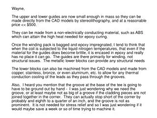
Lower guide details 7.00” 2.48” .125” Rib .54” .50” .625” CL to CL 1.36” .905”
Assemble lower guide block components Lower Guide Lower Guide Block .250” socket head cap screws secure lower guide to block
Attach lower guide block assembly to tee winding form and begin winding conductors .375” socket head cap screws secure lower guide block to tee winding form Conductor wrap transition area for increased insulation .372” .50”
Assemble the upper guide block components Upper Guide .250” socket head cap screws secure upper guide to block 2.34” 3.64” 1.36” .94” Upper Guide Block
Attach upper guide block assembly to the lower guide block assembly .250” socket head cap screws secure upper guide block to lower guide block
Finish final turns by inserting them into the upper guide block grooves and continuing through lower guide block grooves
Attach side plate to block assemblies .250” socket head cap screws secure side plate to the block assemblies
Attach top plate to block assemblies and tee winding form .375” flat head machine screws secure top plate to tee winding form .250” socket head cap screws Secure top plate to block assemblies