Download
1 / 21
210 likes | 336 Vues
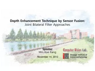
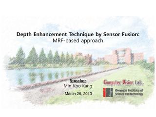
Depth Enhancement Technique by Sensor Fusion: MRF-based approach. Speaker Min-Koo Kang. March 26, 2013. Outline. Review of filter-based method Summary and limitation Related work MRF-based depth up-sampling framework Introduction of state-of-the-art method

E N D
Depth Enhancement Technique by Sensor Fusion: MRF-based approach Speaker Min-Koo Kang March 26, 2013
Outline • Review of filter-based method • Summary and limitation • Related work • MRF-based depth up-sampling framework • Introduction of state-of-the-art method • High Quality Depth Map Upsampling for 3D-TOF Cameras / ICCV 2011 • Future work • Remaining problems • Strategy
Depth upsampling • Definition • Conversion of depth map with low resolution into one with high resolution • Approach • Most state-of-the-art methods are based on sensor fusion technique; i.e., use image sensor and range sensor together Depth map up-sampling by using bi-cubic interpolation Depth map up-sampling by using image and range sensor
Joint bilateral upsampling (JBU) • Representative formulation: • N(P): targetingpixel P(i, j)’sneighborhood. fS(.): spatial weighting term, applied for pixel position P. fI(.): range weighting term, applied for pixel value I(q). fS(.), fI(.) areGaussian functionswith standard deviations, σSand σI, respectively. Upsampled depth map Rendered 3D view *Kopf et al., “Joint Bilateral Upsampling”, SIGGRAPH2007
Is JBUideal enough? • Limitations of JBU: • It starts from the fundamental heuristic assumptions about the relationship between depth and intensity data • Sometimes depth has no corresponding edges in the 2-D image • Remaining problems: • Erroneous copying of 2-D texture into actually smooth geometries within the depth map • Unwanted artifact known as edge blurring High-resolution guidance image (red=non-visible depth discontinuities) Low-resolution depth map (red=zooming area) JBU enhanced depth map (zoomed)
Summary of JBU-based approach • Joint bilateral upsampling approach • Propagates properties from one to an other modality • Credibility map decides system performance • Defining blending function can be another critical factor • Many empirical parameters make the practical automated usage of such fusion filter challenging • Another question is a clear rule on when a smoothing by filtering is to be avoided and when a simple binary decision is to be undertaken
MRF-Based Depth Up-sampling • Diebelet al., NIPS 2005 • Use a multi-resolution MRF which ties together image and range data • Exploit the fact that discontinuities in range and coloring tend to co-align • Pros and cons • Robust to changes in up-sampling scale through global optimization • High computation complexity Data term Smoothness term MRF framework
A novel method based on MRF approach • High Quality Depth Map Upsampling for 3D-TOF Cameras / ICCV 2011
The plot of PSNR accuracy • The combined weighting term consistently produce the best results under different upsampling scale.
NLM regularization term • Thin structure protection • By allowing the pixels on the same nonlocal structure to reinforce each other within a larger neighborhood.
User Adjustments Additional weighting term for counting the additional depth discontinuity information is defined as: After adding the additional depth samples, our algorithm generates the new depth map using the new depth samples as a hard constraint in Equation (4)
Is this method ideal enough? • Noise distribution in depth map: • Practical depth map contains more complicated noise distribution than the Gaussian noise • Neighborhood extension to higher dimension: • Practical depth data is a sequence of successive depth maps • Spatial domain spatial-temporal domain
Spatial-Temporal MRF-Based Depth Map Refinement • Zhu et al., CVPR 2008 • Combine range sensor with stereo sensor • Extend the MRF to temporal domain to take the temporal coherence into account • Pros and cons • Improve accuracy by using temporal coherence • Do not consider changes of depth on time-varying Data term Smoothness term Spatial-temporal MRF structure
Summary of MRF-based approach • MRF-based approach • Maintaining sharp depth boundaries • Easy adoption of several weighting factors • Easy cooperation with user adjustment • Possible improvements in the future • Noise distribution consideration in practical depth data • Temporal smoothness consideration by neighborhood extension