Download
1 / 30
330 likes | 595 Vues
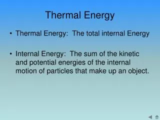
UTES Underground Thermal Energy Storage. (AKA Condensing Heat Exchanger). Presentation Outline. Project Summary Key Dates Budget Critical Function Prototype (CFP) Description Concept Test Results Future Testing and Decisions for Project Summary Questions. Project Summary.

E N D
UTESUnderground Thermal Energy Storage (AKA Condensing Heat Exchanger)
Presentation Outline • Project Summary • Key Dates • Budget • Critical Function Prototype (CFP) • Description • Concept Test Results • Future Testing and Decisions for Project • Summary • Questions
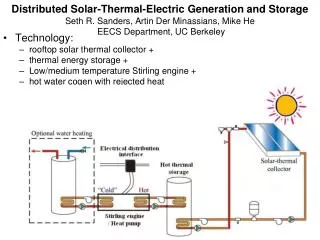
Project Summary • Design, Test and Evaluate Phase Change Enhancements to Underground Thermal Energy Storage • Seasonal Operations • Winter • Creates Heat Sink (Cooled Soil or Ice) • Summer • Utilizes Heat Sink for Air Conditioning
Cooled Air / Glycol Vapor Evaporator Hot Air / Glycol HEAT HEAT Liquid to be pumped to storage Vapor Condensation Complete UTES System
Motivation for UTES Project • Potential to provide all heating and air conditioning needs of a building in a climate such as ours without need for fossil fuels. • Insurance Against Soaring Fossil Energy Prices • A step towards a sustainable systems • Dramatic reduction in a building’s carbon footprint.
Typical Utah Household Power Consumption Project Summary (http://www.utahpower.net/Article/Article35287.html)
Key Dates • Analytic Design Modeling • System Development & CFP Selection • Thermo Siphon CFP • Specifications • Construction • Testing • Evaluation Sept 7 – Dec 12 Sept 7 – Sept 30 Oct 1 – Oct 4 Oct 5 – Oct 18 Oct 19 – Nov 30 Dec 1 – Dec 15
Future Dates • System Component Design • Thermo Siphon • Storage Tank • Distribution System • Controls • System Construction • System Testing Jan 7 – Jan 15 Jan 16 – Feb 15 Feb 16 – Mar 15
Budget Donations $1000 Student Fees $700 $490 Estimated Project Cost $1700 + = $32
Critical Function Prototype • Description • Test • Plan • Results • Future Prototype
CFP Theory The Thermo Siphon will freeze a supply of water throughout the Winter Season to Cool a Building through the Summer Season
What We Learned • Data show that the Thermo Siphon enhances heat transfer from the water to the air at a predicable rate • Test results demonstrate that passive Thermo Siphon operation is very effective in moving heat upward
What We Learned • As a conservative estimate during phase change operation, the heat transfer rate is linearly dependant upon the ΔT between the ambient air and water temperatures
What We Learned • Heat transfer rate into the water is less than 0.1 W/K compared to 1.31 W/K out of the water • The device operates as a thermal diode as desired
Comparison to Calculations • Measured heat transfer rate: 1.31 W/°C • Calculated heat transfer rate: 1.05 W/°C • Over 1 year, current model predicts freezing a cylinder: • 15 cm tall • 50 cm diameter • 30 liters volume of ice (~1 cu ft)
Improving the Model • Thermo Siphon performs better than predicted • Additional effects must be understood and modeled • Wind effects must be taken into account
Future Prototype • Main Components • Storage Tank • Evaporator with Fan • Pumps • Full Integration of the System
Cooled Air / Glycol Vapor Evaporator Hot Air / Glycol HEAT HEAT Liquid to be pumped to storage Vapor Condensation Complete UTES System
Storage Tank • Liquid Refrigerant is Pumped into Bottom • Allows Phase Change of Refrigerant • Vapor Migrates Through the Top Vapor Liquid Liquid
Evaporator Cooled Air / Glycol • Absorption of Heated Air • Phase Change Due to Temperature Change • Glycol will be used in Building System Vapor Evaporator Liquid Hot Air / Glycol
Pumps • Two (2) Liquid Refrigerant Pumps • One Pump Needed for the Storage Tank • One Pump Needed for the Evaporator • Sizes of Pumps to be Determined • Approximately 20 ft of Head @ 1gpm • Variable Frequency Drives Maybe Used
Cooled Air / Glycol Vapor Evaporator Hot Air / Glycol HEAT HEAT Liquid to be pumped to storage Vapor Condensation Complete System • Thermo Siphon • Liquid Pumped to Storage Tank • Liquid Pumped to Evaporator • Phase Changes Exist • Cooling is Achieved
Summary • Project Summary • Key Dates • Budget • CFP • Description • Test Results • Future Testing and Decisions for Project
Kent Udell – Team Advisor udell@mech.utah.edu Vinnie Figlioli vfiglioli@ccimechanical.com 801 580–8573 Kristina Bengtsson kb555@email.com 801 910–6255 James Murray murray106@juno.com 801 618 7208 Russ Olsen russ.olsen@utah.edu 801 703–4921 Michael Merchant jon.merchant@utah.edu 801 755–3987 Dave Stevens greenmoto@yahoo.com 801 232–9519 Lee Sonderegger vlobies@yahoo.com 801 915–6358 Contact Information