Download

1 / 44
440 likes | 609 Vues
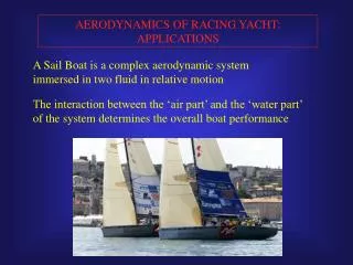
AERODYNAMICS OF RACING YACHT: APPLICATIONS. A Sail Boat is a complex aerodynamic system immersed in two fluid in relative motion . The interaction between the ‘air part’ and the ‘water part’ of the system determines the overall boat performance. DESIGN TOOLS.

E N D
AERODYNAMICS OF RACING YACHT: APPLICATIONS A Sail Boat is a complex aerodynamic system immersed in two fluid in relative motion The interaction between the ‘air part’ and the ‘water part’ of the system determines the overall boat performance
DESIGN TOOLS OVERALL PERFORMANCE PREDICTION AERODYNAMIC TOOLS HULL AND APPENDAGES ------------------ Tank Test CFD SAIL PLAN -------------- Wind Tunnel Full scale test CFD VELOCITY PREDICTION PROGRAM
VELOCITY PREDICTION PROGRAM The VPP provides a steady state speed of the Yacht given the wind direction and magnitude VPP has a two part structure comprised of the HYDRODYNAMIC FORCE MODELS and AERODYNAMIC FORCE MODELS The JOB of the Solution Algorithm is to find that combination of Boat Speed and Heel angle so that aero and hydrodynamic forces are in equilibrium This is a typical polar plot which shows the boat speed for a specific true wind and heading
VELOCITY PREDICTION PROGRAM The “cores” of a VPP are the HYDRODYNAMIC and AERODYNAMIC FORCE MODELS The quality of the solution is dependent on the accuracy of the data of the force models. The models are usually based on both theory and empiricism HYDRODYNAMIC MODEL AERODYNAMIC MODEL • Theoretical relationships • Systematic Tank Test (e.g. Delft series) • Computational Fluid Dynamics • Full scale Test • Wind Tunnel • Computational Fluid Dynamics
HYDRODYNAMIC FORCE MODEL The model has to provide the total drag as a function of boat speed and leeway (angle of attack) Usually the total hydrodynamic drag of the yacht is assumed to be the sum of the following components: • Wave resistance of the canoe body (systematic Tank tests) • Appendage and canoe bodyfriction and form drag (theoretical relationships, empiric coefficients) • Induced drag. Drag associated to the generation of lift (theoretical relationships) • Added resistance in waves. Unsteady motion due to the sea waves (empirical correlations, tank tests)
AERODYNAMIC FORCE MODEL The model has to provide the DRIVING FORCE and the HEELING FORCE as a function of Apparent Wind Speed (AWS) and Apparent Wind Angle (AWA). The polar plot of the sail plan is determined making use of Tunnel Wind Test or CFD analysis VPP The final results of the VPP analyses are estimates of yacht speeds and sailing times during a regatta, the best true indicator of performance. This tool is widely used by the naval architectsin the early stages of the design process to compare a large number of configurations with different overall parameters (such as displacement, length, sail area, ….)
COMPUTATIONAL FLUID DYNAMICS (CFD) IMPROVEMENTS IN COMPUTER PERFORMANCE HAVE MADE THE USE OF Reynolds Averaged Navier-Stokes (RANS) equations FEASIBLE FOR PRACTICAL DESIGN APPLICATIONS LATEST GENERATION OF RACING YACHT HAS GREATLY BENEFITED OF THESE TOOLS, ORIGINALLY DEVELOPED FOR AEROSPACE APPLICATIONS
COMPUTAIONAL FLUID DYNAMICS (CFD) CFD methods allows one to investigate in details the flow fields and to reach a better understanding of the flow phenomena While VPP provides an overall performance prediction, CFD methods allows to reach a refined aerodynamic optimization
COMPUTAIONAL FLUID DYNAMICS (CFD) Principal CFD methods: • Panel method, inviscid potential flow equations. • RANS, Reynolds Averaged Navier-Stokes equations. Capable of solve viscous effects PANEL METHODS Based on the inviscid potential flow equation. Panels are distributed over the model surfaces. Over each panel is distributed a constant source and/or doublet singularity, which satisfies the governing equations Low computaional cost
VISCOUS METHODS • RANS equations spatially discretized on a computational grid. • Grid points clustered in regions where viscous effects are important. • Spatial Discretization: • Finite element • Finite volume • Steady state solution • Unsteady solution: periodic fluctuations of the main fluidynamic quantities Unstructured computational grid Structured computational grid
CFD APPLIED TO HULL AND APPENDAGES HULL KEEL AND RUDDER 3D Analysis: --Plan form --Bulb, winglet --Interaction between keel and wave system 2D Analysis: Laminar foil for low Reynolds number, capable to shift downstream the location of transition onset Wave Resistance Prediction
MAINSAIL GENOA AND MAST CONFIGURATION UPWIND CONDITIONS MAINSAIL WITH GENNAKER OR SPINNAKER --------------- Large separations and unsteadyness DOWNWIND CONDITIONS CFD APPLIED TO SAILS
CFD APPLIED TO RACING YACHTS THE AERODYNAMIC OPTIMIZATION IS A COMPLEX TASK REQUIRING KNOWLEDGE OF AERODYNAMICS AND HOW TO ACT ON THE GEOMETRY IN ORDER TO IMPROVE THE PERFORMANCE. OPTIMIZATION TECHNIQUES CAN BE USEFUL IN THIS KIND OF DESIGN PROCESS
OPTIMIZATION METHODOLOGIES Design process as optimization of transfer function: Pj=Pj(Xi) Pj Performance parameters j=1,M Xi Geometrical parameters i=1,N • Geometrical parameterization: • Bezier Curves • NURBS • Optimization techniques: • Gradient Based Methods • Design of Experiments • Evolutionary algorithms
OPTIMIZATION METHODOLOGIES Gradient Based Methods • Exploration of original configuration neibourhood • Evaluation of the gradient of TF • Solution moved toward maximum gradient direction • Time cost depending on initial configuration choice • Few iterations required • Widely used for local optimum searching
3 Levels - Full Resolution N. of input parameters N. Of runs 3 15 6 45 OPTIMIZATION METHODOLOGIES Design of Experiments (DOE) • Transfer function approximated with a polynomius: • P= β0+ β1X1+… β11X12+ …β12X1X2 +…β123X1X2X3… • Evaluation of transfer functions on a set of configurations • DOE Theory Determination of ß coefficients through least squares regression
Time Cost N. of input parameters N. Of runs 6 150 OPTIMIZATION METHODOLOGIES Genetic Algorithms • Based on Darwin’s evolutionary theory • Initial set of design configurations (population) randomly selected • Direct evaluation of TF for each configuration • Three genetic operators: selection, recombination and mutation • Sequential generation of improved populations
Advantages Drawbacks Gradient Based Methods Low computational cost Only local optimum Design of Experiments Suitable for simple multipeak TF TF approximation Genetic Algorithms Suitable for complex multipeak TF High computational cost OPTIMIZATION METHODOLOGIES Comparison between different strategies
ON THE USE OF CFD TO ASSIST WITH SAIL DESIGN INTRODUCTION TRADITIONALLY THE SAIL DEVELOPMENT IS DELEGATED TO THE SAILMAKERS EXPERIENCE COMPUTATIONAL FLUID DYNAMICS CAN BE AN INNOVATIVE TOOL THAT ALLOWS TO TEST AND COMPARE A LARGE NUMBER OF CONFIGURATIONS IN A RELATIVELY SHORT AMOUNT OF TIME
ON THE USE OF CFD TO ASSIST WITH SAIL DESIGN • Aerodynamic design of an IACC sail plan in upwind condition. • Optimal Sails profiles depending on: • Hull and appendages features • Wind speed and angle • Sailing style and trim • Critical for: • Manufacturing problems • Sail shapes not fixed, varying with wind pressure and sail trim
DESIGN CRITERIA • Sails are often compared to aircraft wings. • Unfortunately classic aeronautical design criteria are only partially useful: • Contrary to wings, sails must work in a wide operative range (i.e. angle of attack) • The goal in the aeronautical design is to minimize the losses (drag). In sail design the goal is to maximize the driving force, without taking into account losses. • The classic Lift-Force projection must replaced with the sailing aerodynamics terms “Driving-force Heeling-Force” • The flow is often separated (depending on the angle of attack)
DESIGN CRITERIA • Design Operating Conditions: • True Wind Speed • Apparent Wind Angle • Input data: • Initial configuration recovered from pictures (deformed shape) • Righting Moment available Under fundamental hypothesis of a constrained Heeling Moment, the GOAL is to find a maximum driving force configuration.
GEOMETRY DATA ACQUISITION • Superimposition of Bezier curves. • Principal parameters used to describe the profile: • CAMBER • DRAFT • Entry Angle • Exit Angle • Twist Angle
NAVIER-STOKES Solver “Hydro” • 3D, fully viscous, multi-grid, multi-block code developed by the University of Florence • Acceleration techniques employed: • Local time-stepping • Residual smoothing • Multi-grid Full Approximation Storage (FAS) • Boundary Conditions: • Solid walls: no-slip condition • Inlet: total pressure and flow angles • Outlet: static pressure • The Earth’s boundary layer can be taken into account imposing spanwise variable inlet conditions.
Mainsail Genoa GRID GENERATION The first step is to generate a computational grid around the sail plan. The computational grid represents the domain where the solver computes the solution. • The size (number of points) of the computational grid has to fulfill three main requirements: • To solve the flow phenomena of interest (e.g. boundary layer) • To compute solutions sufficiently grid-independent • To match computational times to design needs
GRID GENERATION The boundaries have to be defined far enough from the sails, where the flow is indisturbed.
HORIZONTAL SECTION OF THE GRID Genoa Mainsail GRID GENERATION The Grid consists of three block. Structured H-type grids were employed in computations. The grid generation is based on an elliptic procedure on 2D grids which are subsequently stacked in the vertical direction.
GRID GENERATION 2 200 000 grid point was judged to be a good compromise (memory requirements of about 650MB) for mainsail-genoa configuration For a complete mast model, a viscous grid with 285 x 129 x 93 grid points in the chordwise, chordwise-orthogonal, and spanwise directions, was used (3 400 000 grid point, 1000 MB memory requirements) Details of the viscous grid around the mast Grid points clustered near the solid walls in order to solve the boundary layer
VISCOUS SOLUTION The RANS codes allow to take into account the viscous effect such as boundary layer, separation bubble. Compared to other design tools, the RANS solution allows to investigate in detail the flow structures
PARAMETRIC ANALYSIS The first analysis presented is obtained through a parametric variation of the Genoa Camberon the whole span from the initial value 11% up to 21%. The design Apparent Wind Angle (AWA) is 16 deg.
PARAMETRIC ANALYSIS Static pressure distribution on the genoa profile The results of the computations, for incompressible flow, are the velocity vectors and the static pressure field (one value for each grid point) LEADING EDGE TRAILING EDGE
PARAMETRIC ANALYSIS Obviously the Camber variations from its initial valueinvolve both driving force and heelingmoment changes.
PARAMETRIC ANALYSIS Which is the Optimal Genoa Camber value? -- The optimal Camber is a comprime solution between heeling-moment and driving force. -- It is necessary to evaluate the trade-off between heeling moment anddriving force. -- To this aim the initial Heeling Moment (constrained) has to be re-established through theMainsail Twist Distribution -- This is a well-known practice for reducing the heeling moment used by every yachtsmen Heeling force
PARAMETRIC ANALYSIS --To re-establish the initial Heeling Moment (which is the optimization process constraint) the mainsail twist is varied --Three parametric curve for three separate mainsail twist
Chm TWS PARAMETRIC ANALYSIS IT SHOULD BE NOTED THAT THE HEELING MOMENT COEFFICIENT IS CORRELATED TO THE WIND SPEED Heeling Moment Coefficient definition: Where: Hm: Heeling Moment Chm: Heeling Moment Coefficient SA: Sail Area dm: Distance between CLR and mast-head SINCE Hm IS UPPER BOUNDED BY THE BOAT STABILITY, THE GREATER THE WIND SPEED (AWS), THE LOWER THE HEELING MOMENT COEFFICIENT (Chm) MUST BE
PARAMETRIC ANALYSIS Light Wind Moderate Wind Heavy Wind Which is the Optimal Genoa Camber value? -- Points A,B and C represent the optimal camber values for three separate wind magnitude
GENOA CAMBER PARAMETRIC ANALYSIS PLOTTING THE DRIVING FORCE INA THIRD DIMENSION WITH THE AID OF THE CONTOUR LINES (lines at constant driving force) GIVEN THE RESULT OF THE ANALYSIS, THE ESSENTIAL FEATURES OFSAILS IS ITS ABILITY TO BEADJUSTED TOMATCH THE WIND SPEED CHANGES
GENOA CAMBER PARAMETRIC ANALYSIS SAIL REQUIREMENTS: ABILITY TO BEADJUSTED TOMATCH THE WIND SPEED CHANGES NEED FOR MANY SAILS FOR EACH WIND SPEED • In upwind conditions, an America’s Cup Class has 2/3 different mainsail and 5/6 different genoa: • Genoa code 1: <6 kn TWS • Genoa code 2: 8 kn TWS • Genoa code 3: 12 kn TWS • Genoa code 4: 16 kn TWS • Genoa code 5: 20 kn TWS
MAINSAIL CAMBER PARAMETRIC ANALYSIS THE ANALYSIS HAS BEEN REPEATED FOR THE MAINSAIL CAMBER (AWA 16 deg)
MAINSAIL CAMBER PARAMETRIC ANALYSIS GIVEN THE RESULT OF THE ANALYSIS, MAINSAIL SHOULD BE FLATTER THAN GENOA. Main Head Genoa Head Genoa Mainsail This fact can be explained by taking into account the load distribution: The aerodynamic load on the Genoa is greater than the load on the mainsail Main Base Genoa Base
LIGHT WIND CONDITION OPTIMUM SPANWISE CAMBER DISTRIBUTION To go further in the analysis is it possible to consider the optimum spanwise distribution of the Genoa camber CAMBER should increase with increasing height
MODERATE WIND CONDITION OPTIMUM SPANWISE CAMBER DISTRIBUTION To go further in the analysis is it possible to consider the optimum spanwise distribution of the Genoa camber CAMBER should decrease with increasing height
OPTIMUM SPANWISE CAMBER DISTRIBUTION SPANWISE LOAD DISTRIBUTION --Light Wind: increasing load with increasing height --Moderate Wind: decreasing load with increasing height Genoa Twist distribution fixed Load on the Genoa is induced by the Mainsail twist distribution
CONCLUSION From the 1983 turning point in the America’s Cup hystory to today, the use of CFD in the yacht design process has quickly increased While no CFD methos should claim to replace other design tools (wind tunnel, tank test…), CFD play an important role in a modern design process Improvements in computer performance have made the use of RANS the main CFD tool for practical design applications, opening new frontiers in racing yacht design