Download
1 / 27
270 likes | 421 Vues
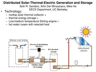
OGZEB Hybrid Thermal Electrical Energy Storage System Fall 2013-Final Presentation. Sponsors/Advisors : Dr. Li, Dr. Ordonez, Dr. Zheng Date : 12-5-2013. Team members : Corey Allen, Anthony Cappetto , Lucas Dos Santos, Kristian Hogue, Nicholas Kraft, Tristian Jones, Artur Nascimento.

E N D
OGZEB Hybrid Thermal Electrical Energy Storage System Fall 2013-Final Presentation Sponsors/Advisors: Dr. Li, Dr. Ordonez, Dr. Zheng Date: 12-5-2013 Team members: Corey Allen, Anthony Cappetto, Lucas Dos Santos, Kristian Hogue, Nicholas Kraft, Tristian Jones, ArturNascimento ArturNascimento
Outline • Project Scope/Objectives • System Design & Analysis • Prototype Integration & Testing • Tentative Procurement Options • Future Plans • Conclusion • Questions ArturNascimento
Project Scope • Design energy storage system to store excess power generated by the house’s solar cells to be used at night. • System will consist of an array of batteries and a thermal energy storage system. ArturNascimento
Objectives • Develop a model of the house’s power needs to determine the best type, number, and arrangement of batteries for the house • Create an Ice Thermal Storage System in parallel to the house main air conditioning system. ArturNascimento
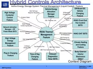
Thermal Storage Design ArturNascimento
Final Design Concept • Chiller cools water during the day. • Water cooled inside of tanks to be installed inside an air exchange box. • Tanks are designed to maximize heat transfer when air is drawn past them with the help of fins. • Air run directly over tanks into the house. ArturNascimento
Original Design Visualization Finned Water Tanks (3) Air In Air Out Cold Glycol Into Box Warm Glycol Out Cool Air in Chiller Battery Container Nick Kraft
Fluid Process Flow Diagram Fins Water Tanks Cold Glycol from Chiller Warm Glycol to Chiller Cold air out Hot air in ArturNascimento
Design Changes or Additions • Instead of using wood for construction of the air exchange box, will be used sheet metal with heavy thermal insulation around the outside perimeter. • To integrate the system in the house, the same AC system ducts will be used. • When the air conditioner is turned off a fan installed will impel the air into the air exchanger box. • A small door will be programmed to open or close at the airflow entrance and exit to close off the system during the daytime chilling process. • Heat rejection from chiller funneled into battery box for climate control Nick Kraft
House Integration Enough room for system as designed Air ducts in and out of house thermalsystem Nick Kraft
Design Addition Chiller heat rejection to battery box Nick Kraft
Detailed Design-Aluminum Tank Configuration Nick Kraft
Detailed Design-Copper Coil Nick Kraft
Ice Melt Analysis • For the analysis of the fin heat transfer, the assumption of an adiabatic fin tip was made due to the fin tip being up against the inside surface of the wood box. • Assumed ambient temperature of 20 C and ice temperature of 0 C. • Water latent heat of fusion = 334 kJ/kg • Total heat loss required to melt 400 L ice = 133.6 MJ • The heat loss rate through the NON-FINNED area of 3.13 square meters will be approximately 838W. • The total heat transfer for a fin (adiabatic tip) is given by: • The total heat transfer for a single aluminum fin was found to be 40.5 W. • If the total heat transfer for a single fin is multiplied by the number of fins (48 total), a total fin heat transfer rate can be calculated to be 1942 W. • If both the non-finned surface heat transfer and finned heat transfer are added together the combined total heat transfer (H) can be calculated to be 2780 W. • Finally, the melting time can be calculated: Nick Kraft
What has been done • Using MATLAB we were about to run battery simulations of the house • Gathered Load Data (for a house of similar dimensions) • Acquired weather data to use for simulations • Ran simulations to give us an idea of battery lifetime • Did a cost analysis of different type of batteries for the house • Look at 3 different types of batteries • Compared to batteries life span • Also look at different configurations to increase power • Made a recommendation based on this analysis • Design a way to keep the batteries at a more stable temperature • Will be using a Arduino Uno Microprocessor with motors • The bulk of this part will be done in the upcoming semester Anthony Cappetto
Battery Temp Regulation Cold Air from system used to cool batteries Heat rejection from chiller used to warm batteries Valves Battery Container Temperature Sensor and valve actuator Kristian Hogue
Battery Temp Regulation Thermal Battery Management Specifications - Arduino Uno Project Board - 14 Digital outputs/inputs - 6 of 14 are Digital PWM - 6 analog input pins - This board will be programed to control the valves into the battery boxes Kristian Hogue
Other items • LCD screen to • display the temperature • 2 Stepper motors • to control the valves • Thermostat or Thermistor • to observe the temperature • of the box Kristian Hogue
Additional Design Aspects • Roofing insulation will isolate the air exchange and battery boxes from the outside, to minimize heat transfer to environment • Air exchange box to have drain to remove condensation • If batteries begin to overheat, valve opens to allow cold air from the system to cool the batteries. • If batteries fall under minimum temperature, hot air from chiller input to battery box • Use of a filter to clean the air coming from the outside into air exchanger box, also removes odors • Doors to control air flow into/from house Lucas Dos Santos
Additional Components • Chiller and fan to be purchased according to specs • Current design utilizes a Glycol Chiller and 870 CFM fan • Secondhand products may be available (Recycled products are a plus for the OGZEB) • Sheet metal and insulation can be bought from local hardware stores • Aluminum for water tanks available online Lucas Dos Santos
Prototype Integration & Testing • Original Plan is to put the thermal storage system in series with the main HVAC duct and in parallel with the main A.C. system by cutting into the main duct and attaching our own duct • The main A.C. system will run during the day and airflow will be impelled through the main house duct only • At night our fan will turn on which will impel the house air only through our duct which is attached to the inlet and outlet of both our system and the main duct • The prototype will be built first and tested using outside air before cutting into the main duct and installing the full system Lucas Dos Santos
Cost Analysis (Thermal) Lucas Dos Santos
Problems Encountered • Sponsor disagrees with battery selection, citing possible maintenance costs • Discussion and further analysis necessary • Sponsor concerned with keeping the batteries warm during winter • Possible solution created by using waste heat from chiller • Lack of defined budget is hindering team from continuing • Meeting with all sponsors and faculty to take place next to discuss budget issue Tristian Jones
Conclusion • Further discussion necessary to determine correct battery selection • Thermal energy storage system design concept complete • Size of system will be determined based on available budget, to be decided next week • Suppliers and parts located Tristian Jones
Future Plans • Meet with all faculty sponsors and advisors to determine budget • Determine possible size of system • Order materials • Install battery array • Begin to build the energy management system prototype. • Evaluate potential of adapting system to work during the winter, when AC use is unnecessary. Tristian Jones
Future Plans • Try to improve the energy management system for the battery system • prevent over charging of the batteries. This decreases battery life • Create future management system for possible grid connection • Programming of the microprocessor • This will control the temperature of the batteries and extend battery life • Connecting back to the grid • Talking to the power company to get minimum requirements • Research a bi-direction converter used for connection to grid Corey Allen