Download
1 / 15
150 likes | 467 Vues
Designing MIMO Modems on FPGAs Using Simulink. Bradley Comar MITRE Corporation. Problem. Severe multipath fading and non-line-of-sight environments cause link corruption or failure for many communication systems.

E N D
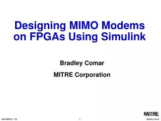
Designing MIMO Modems on FPGAs Using Simulink Bradley Comar MITRE Corporation
Problem • Severe multipath fading and non-line-of-sight environments cause link corruption or failure for many communication systems. • Multiple-input multiple-output (MIMO) systems exploit multipath to create greater theoretical capacities by means of space-time coding. • Does space-time coding work on real modems over real multipath channels?
Potential Solution • Both Altera and Xilinx offer development kits that claim to allow the Signal Processing engineer to quickly and easily design and test projects in Simulink. Projects would be compiled and loaded onto FPGAs. • The Altera Stratix development kit is chosen to implement MIMO coded modems. These modems will be used to validate MIMO’s performance enhancing claims.
The Space-Time Code 2x2 Unitary Space-Time Modulation: -Group code determined by input data -Transmitter sends -Receiver recovers
Space-Time Code Design Using Simulink to design and test the encoder:
Space-Time Code Design Using Simulink to design and test the decoder:
Modem Design Using Simulink to design and test the transmitter:
Modem Design Using Simulink to design and test a modulator:
Bit Error Rate Tester Using Simulink to design and test a BER tester:
Debugging in Simulink Using Simulink scope here to debug the symbol synchronizer:
Altera Dev Board Interferer tx RF front end rcv RF front end Altera Dev Board TX Altera Dev Board RX + + tx RF front end rcv RF front end Shield Test Setup Testing MIMO modems indoors using separate FPGA development boards for transmitter, receiver, and interferer :
Test Setup LO interferer transmitter receiver shield
Results -The MIMO system outperforms the SISO system in LOS and non LOS testing. -There are wide variations in the MIMO plot which could be due to sporadic loss of symbol lock and lack of AGC.
Results -The MIMO system outperforms the SISO system at all the antenna spacing measurements. -There are wide variations in the MIMO plot which could be due to sporadic loss of symbol lock.
Conclusion • Simulink proves to be an easy environment in which to program and debug modem code for FPGAs. No prior knowledge of VHDL is needed. This is a great tool for the Signal Processing engineer. • This tool is used to investigate MIMO space-time coding. Initial results show that these codes can be used to enhance BER performance for modems in laboratory environments.