System Architecture Directions for Networked Sensors
460 likes | 600 Vues
System Architecture Directions for Networked Sensors. Qiuhua Cao (qc9b@cs) Computer Science Department University of Virginia. Outline. Hardware Organization of Berkeley Motes Critical Issues of Sensor Networks Does an OS for the Motes exsit? Design Goals of TinyOS Concepts in TinyOS

System Architecture Directions for Networked Sensors
E N D
Presentation Transcript
System Architecture Directions for Networked Sensors Qiuhua Cao (qc9b@cs) Computer Science Department University of Virginia
Outline Hardware Organization of Berkeley Motes Critical Issues of Sensor Networks Does an OS for the Motes exsit? Design Goals of TinyOS Concepts in TinyOS Examples Evaluation and Critiques
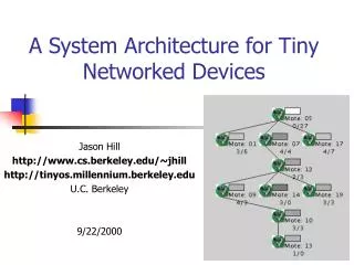
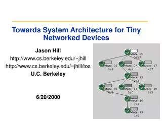
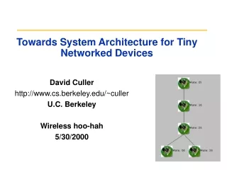
Hardware Platform-Motes • Assembled from off-the-shelf components • 4Mhz, 8bit MCU (ATMEL 90LS8535) • 512 bytes RAM, 8K ROM • 900Mhz Radio (RF Monolithics) • 10-100 ft. range • Temperature & Light Sensor • LED outputs • Serial Port
Critical Issues for Sensor Networks • Highly Limited Device • power, memory, bandwith • Inherently Distributed • large number of nodes coordinate, cooperate with each other to fulfill an job • Devices themselves are the infrastructure • ad hoc, self-organized • Highly Dynamic • failure in common • variation in connectivity over time
Does an OS for the Motes exist? • Traditional OS design • wait request, act, respond loop • monolithic event processing • full thread/socket POSIX regime • Alternative • concurrency and modularity • never poll, never block • data flows, events, power management interact
Design Goals of TinyOS • Concurrency-Intensive Operations • flow information from place to place on-the-fly • Example: simultaneously capture data from sensors, processing the data, then send out to the network
Design Goals of TinyOS (cont.) • Limited Physical Parallelism and Controller Hierarchy • Less independent controllers • Less processor-memory-switch level • Sensor and Actuator directly interact with the single-chip micro controller
Design Goals of TinyOS (cont.) • Diversity in Design and Usage • Sensor network application specific design • But wide range potential applications • deep modularity of software needed
Design Goals of TinyOS (cont.) • Robust Operations • Cross devices redundancy prohibitive • Individual reliable devices desired • Application tolerant individual device failures
Concepts in TinyOS • Application = graph of components + scheduler • Example: INT_TO_LEDS MIAN COUNTER INT_TO_LEDS CLOCK LED
Concepts in TinyOS (cont.) • Component • Implementation (.c file) • Frame • a set of commands • a set of handlers • a set of tasks • Interface (.comp) • Description file (.desc)
Concepts in TinyOS (cont.) • Frame • Contains all permanent state for component (lives across events, commands, and threads) • Threads, events, and commands execute inside the component’s frame • Only one per component • Like static class variables, not internal class variables. • Fixed size • Statically allocated at compile time
Concepts in TinyOS • Frame example: • Frame declaration #define TOS_FRAME_TYPE AM_obj_frame TOS_FRAME_BEGIN(AM_obj_frame) { int addr; char type; char state; char* data; char msgbuf[30]; } TOS_FRAME_END(AM_obj_frame); • Use of frame Variables: VAR(state) = 0;
Commands: • Commands deposit request parameters into its frame • Commands can call lower level commands • Commands can post tasks • Commands no-blocking • Commands needed to return status • Declaration TOS_COMMAND(cmd_name)(cmd_args_list); • USE: TOS_CALL_COMMAND(cmd_name)(cmd_args_list);
Events • Deposit information into frame • Events can call lower level commands • Post tasks and fire higher level events. • Events can not be signaled by commands, • Declaration char TOS_EVENT(evnt_name)(evnt_arg_list); • Use TOS_SIGNAL_EVENT(evnt_name)(evnt_arg_list);
Tasks • Tasks perform work that is computationally intensive. • FIFO scheduler • Run-to-completion • Non-preemptable among tasks (concurrent) • Preemptable by events • Task declaration: TOS_TASK(task_name){….} • Posting a task: • Asynchronous call to schedule the task for later execution • USE: TOS_POST_TASK(avg_task);
Commands, Events, Tasks Both event and cmd can schedule tasks • Relationship Graph Higher Level Component Commands can not signal Events Issue cmds Signal events Tasks preemptive by Envents Lower Level Component Tasks non preemptive by Tasks
send_msg(addr, type, data) power(mode) msg_send_done (success) msg_rec(type, data) init Internal State Messaging Component send_msg_thread TX_packet(buf) Power(mode) RX_packet_done (buffer) init TX_packet_done (success) An Component Example Cmd Issued Cmd accepted Events handled Events signaled
An Component Example (cont. ) • .comp file interface definition TOS_MODULE name; ACCEPTS{ command_signatures}; HANDLES{ event_signatures}; USES{ command_signatures}; SIGNALS{ event_signatures};
An Component Example (cont. ) • .comp file interface definition //ACCEPTS: char TOS_COMMAND(AM_send_msg)(int addr, int type, char* data); void TOS_COMMAND(AM_power)(char mode); char TOS_COMMAND(AM_init)(); //SIGNALS: char AM_msg_rec(int type, char* data); char AM_msg_send_done(char success);
An Component Example (cont.) //HANDLES: char AM_TX_packet_done(char success); char AM_RX_packet_done(char* packet); //USES: char TOS_COMMAND(AM_SUB_TX_packet)(char* data); void TOS_COMMAND(AM_SUB_power)(char mode); char TOS_COMMAND(AM_SUB_init)();
An Component Example (cont.) • .c file frame, commands, events implementation #define TOS_FRAME_TYPE AM_obj_frame TOS_FRAME_BEGIN(AM_obj_frame) { char state; TOS_MsgPtr msg; }TOS_FRAME_END(AM_obj_frame); // This task schedules the transmission of the Active MessageTOS_TASK(AM_send_task){ //construct the packet to be sent,fill in dest and type if(!TOS_CALL_COMMAND(AM_SUB_TX_PACKET)(VAR(msg))) { VAR(state) = 0; TOS_SIGNAL_EVENT(AM_MSG_SEND_DONE)(VAR(msg)); return; }}
.c file frame, commands, events implementation // Command to be used for power management char TOS_COMMAND(AM_POWER)(char mode){ TOS_CALL_COMMAND(AM_SUB_POWER)(mode); VAR(state) = 0; return 1; } // Handle the event of the completion of a message transmission char TOS_EVENT(AM_TX_PACKET_DONE)(TOS_MsgPtr msg){ //return to idle state. VAR(state) = 0; //fire send done event. TOS_SIGNAL_EVENT(AM_MSG_SEND_DONE)(msg); return 1; }
An Component Example (cont. ) • .desc file • component modules specified • the wiring of commands and events across component interfaces • Example: include modules{ module list }; connection list
Storage Model • One frame per component, shared stack Previous frame %fp(old %sp) Current frame data variable %sp Stack Growth Next frame
Storage Model (cont.) • Message Buffer • Strict alternating ownership protocol • Only TOS_MSG type pointer across component send_msg AM AM is owner of message buffer, the requesting component can not access this message buffer send_done AM gives up the owner of message buffer,
Storage Model (cont.) char TOS_COMMAND(INT_TO_RFM_OUTPUT)(int val){ ... if (!VAR(pending)) { VAR(pending) = 1; message->val = val; message->src = TOS_LOCAL_ADDRESS; if (TOS_COMMAND(INT_TO_RFM_SUB_SEND_MSG)(TOS_BCAST_ADDR,AM_MSG(INT_READING), &VAR(data))) { return 1; } else { VAR(pending) = 0; /* request failed, free buffer */ } } return 0; }
Scheduler • Two-level scheduling structure • Tasks, Events • FSM execution model • Each task is like a state in the state machine, which the events are like input signals • Events model • When there is no event, CPU is put in idle
An example of Execution Model Get_Light Clock Event / Light Request Command Light done event / Msg send command Sleep Send_Msg Msg sent event / Power down command
Add a task Calc. Average Get_Light Light done event / Post Task Thread Schedule / Msg send command Clock Event / Light Request Command Sleep Send_Msg Msg sent event / Power down command
An Composition Example sensing application Routing Layer routing Messaging Layer packet Radio Packet byte Radio Byte photo Temp SW HW bit RFM clocks ADC I2C
An Composition Example Send_message sensing application Routing Layer Messaging Layer Radio Packet Radio Byte photo Temp SW HW RFM clocks ADC I2C
An Composition Example TX_Packet sensing application Routing Layer Messaging Layer Radio Packet Radio Byte photo Temp SW HW RFM clocks ADC I2C
An Composition Example TX_byte sensing application Routing Layer Messaging Layer Radio Packet Radio Byte photo Temp SW HW RFM clocks ADC I2C
An Composition Example TX_Bit_Event sensing application Routing Layer Messaging Layer Radio Packet Radio Byte photo Temp SW HW RFM clocks ADC I2C
An Composition Example TX_Bit_Done sensing application Routing Layer Messaging Layer Radio Packet Radio Byte photo Temp SW HW RFM clocks ADC I2C
An Composition Example TX_Byte_Done sensing application Routing Layer Messaging Layer Radio Packet Radio Byte photo Temp SW HW RFM clocks ADC I2C
An Composition Example TX_Packet_Done sensing application Routing Layer Messaging Layer Radio Packet Radio Byte photo Temp SW HW RFM clocks ADC I2C
An Composition Example Msg_Send_Done sensing application Routing Layer Messaging Layer Radio Packet Radio Byte photo Temp SW HW RFM clocks ADC I2C
Evaluation • meet power constraints?
Battery Lifetime for sensor reporting every minute Duty Cycle Estimated Battery Life Full Time Listening 100% 3 Days Full Time Low Power Listening 100% 6.54 Days Periodic Multi-Hop Listening 10% 65 Days No Listening 0.01% Years Evaluation • meet power save?
Evaluation • meet memory constraints?
Evaluation • Meet concurrent-intensive operations? • Event-driven architecture • Efficient interrupts/events handling (function calls, no user/kernel boundary) • Modularity? • Function call (event, command) interface between components
Critique • Real-time not addressed • Non-preemptable FIFO task scheduling • NO real-time guarantees or overload protection • Tasks are dispatched to either software or hardware to best utilize the whole system resources but in TinyOS, all tasks go into software. • Adding event queues at the lowest layers can reduce the external event losses • The OS should collect runtime profiles and statistics, perform periodic system maintenance operations and maintain system level power state • No opposite argument
Thanks!! Any Question??