Download
1 / 38
380 likes | 491 Vues
Learn about data packets, NICs, analog and digital signals, OSI model, protocols, and more in computer networking. Explore how data is transmitted and the role of key components in network communication.

E N D
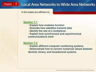
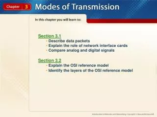
Section 3.1 • Describe data packets • Explain the role of network interface cards • Compare analog and digital signals • Section 3.2 • Explain the OSI reference model • Identify the layers of the OSI reference model
Section 3.3 • Explain the role of protocols • Identify industry standard protocol stacks • Describe how protocols work within a reference model
pp. 70-76 How Network Traffic Gets from Here to There 3.1 Guide to Reading Main Ideas Two important components needed to transfer data are data packets and network interface cards. Data can be transmitted using a digital or analog signal. Key Terms data packet cyclical redundancy check (CRC) bus parallel transmission serial transmission analog broadband transmission digital baseband transmission multiplexing
pp. 70-76 How Network Traffic Gets from Here to There 3.1 Data Packets Networks are very fast, but there is a limit to the amount of traffic networks can transport at one time. The solution to this problem is to break this traffic into small pieces known as data packets. A data packet, also called a packet, is a very small part of the entire piece of data that needs to be sent. data packet Data that consist of three parts—a header, the data itself, and a trailer. (p. 70)
pp. 70-76 How Network Traffic Gets from Here to There 3.1 Data Packets A cyclical redundancy check (CRC)is performed at the sending and receiving computers to make sure the data packet arrived with no errors. cyclical redundancy check (CRC) Error checking used in networks. A sending node performs a mathematical calculation on the packet and the result is attached to the packet’s trailer. The receiving node performs the same calculation on the packet it received. If the calculations differ, the CRC signals the source computer to retransmit the packet. (p. 71)
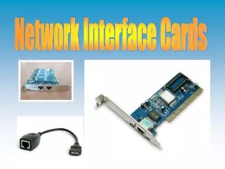
pp. 70-76 How Network Traffic Gets from Here to There 3.1 Data Packets • The job to neatly chunk, address, and deliver the information in a network is handled by the network interface card (NIC) in each computer. • The NIC does the following: • Provides the source, or hardware, address of the computer. • Prepares the data from the computer for the network cable. • Sends data to another computer. • Controls the flow of data between the computer and the cabling. • Receives incoming data from another computer. • Translates electrical impulses from the cable into binary code that the computer understands.
pp. 70-76 How Network Traffic Gets from Here to There 3.1 Data Packets Within the computer itself, information travels along pathways known as buses. A bus consists of multiple “lanes” (wires) set side by side. bus A data pathway that connects components in a computer using parallel cabling or wire. (p. 72)
pp. 70-76 How Network Traffic Gets from Here to There 3.1 Data Packets Data packets travel in parallel transmission within the computer, but in serial transmission on a cable. Data on a network move from the “multilane” computer cable to a “single-lane” network cable. parallel transmission The orderly procession of transmitted data in computers in which groups of bits are transferred simultaneously side by side over two or more wires. (p. 72) serial transmission The procession of transmitted data in which bits are sent over network cables and travel bit by bit one at a time. (p. 73)
pp. 70-76 How Network Traffic Gets from Here to There 3.1 Transmitting Data Packets Baseband and broadband are two techniques used to transmit data packets over cable. Bandwidth is the maximum speed at which a particular communications medium, such as cables, can transfer information. Bandwidth measurement depends on the type of signal (analog or digital) and the media used to carry the information. Type of Signal (analog or digital) + Type of Media = Bandwidth
pp. 70-76 How Network Traffic Gets from Here to There 3.1 Transmitting Data Packets In an analog signal, information travels as a continuously changing wave. This signal cycles up and down in a wavelike pattern. analog A signal that travels as a continuously variable wavelike pattern. (p. 74)
pp. 70-76 How Network Traffic Gets from Here to There 3.1 Transmitting Data Packets Broadband transmissions can be divided into multiple channels separated by small bands of unused frequencies to avoid one channel interfering with the signal being transmitted on its neighbors. Broadband is unidirectional—it moves in one direction only. To send and receive, the communications bandwidth is divided into two channels, one for each direction. broadband transmission Transmissions that rely on an analog signal, a range of frequencies, and a communications medium. Broadband signals can be divided into multiple channels separated by small bands of unused frequencies to avoid interference. (p. 74)
pp. 70-76 How Network Traffic Gets from Here to There 3.1 Transmitting Data Packets An example of broadband transmissions are digital signals. Digital signals encode information numerically, using 0s and 1s. These simple signals convey information in separate on/off pulses over the communications medium, such as cables.
pp. 70-76 How Network Traffic Gets from Here to There 3.1 Transmitting Data Packets Basebandtransmissions send digital signals over a single channel. Multiple transmissions can be sent through the channel simultaneously through a technique known as multiplexing. baseband transmission Transmissions of digital signals over a single channel, typical of most current LANs. One signal at a time travels over the network cable. (p. 75) multiplexing Multiple transmissions sent through a channel simultaneously and are interwoven into a single signal. (p. 75)
pp. 70-76 How Network Traffic Gets from Here to There 3.1 Transmitting Data Packets This is an example of multiplexing, in which several signals from different sources can be fed into one cable for transmission.
pp. 78-85 Network Models 3.2 Guide to Reading Main Ideas Network models describe how different network devices communicate with each other. The OSI model consists of seven layers that describe the tasks a network component must handle. Key Terms protocol Open Systems Interconnection (OSI) reference model interface session data frame Transmission Control Protocol/Internet Protocol (TCP/IP) reference model Advanced Program to Program Communications (APPC) Internetworking
pp. 78-85 Network Models 3.2 Models Versus Protocols To ensure that products from various manufacturers can communicate with each other, network models have been created. A protocol, which is part of software, is what makes a network work. The model describes what needs to be done, and the protocol performs the work. protocol Rules that define how network devices communicate with each other and perform specific tasks. (p. 78)
pp. 78-85 Network Models 3.2 The OSI Reference Model The Open Systems Interconnection (OSI) reference model consists of seven layers that define how data are sent from a computer, through the network, and into a receiving computer. Understanding each layer and how each one interacts with other layers helps you understand how networks operate. Open Systems Interconnection (OSI) reference model An international standard that is a guide for networking. Defines how data are sent from a computer, through the network, and into a receiving computer. Also called the OSI model. (p. 79)
pp. 78-85 Network Models 3.2 The OSI Reference Model The OSI model provides a description of how network hardware and software work together in a layered fashion to make communications between computers possible. Each layer includes different network activities, equipment, or protocols.
pp. 78-85 Network Models 3.2 The OSI Reference Model Layers are separated from each other by boundaries calledinterfaces. interface The connection that provides communication between layers. It also shields neighboring layers from the details of how services are implemented. (p. 80)
pp. 78-85 Network Models 3.2 OSI Layers Beginning at the top of the OSI model (Layer 7), we work down to the bottom (Layer 1). The lower layers in the OSI model support the tasks that are performed at the upper layers.
pp. 78-85 Network Models 3.2 OSI Layers
pp. 78-85 Network Models 3.2 OSI Layers Layer 5, the Session Layer, allows two applications on different computers to open, use, and close a connection called a session. The Session Layer is responsible for managing this dialogue. session A highly structured dialog between two workstations. (p. 81)
pp. 78-85 Network Models 3.2 OSI Layers Layer 2, the Data Link Layer, sends data frames from the Network Layer to the Physical Layer. A data frame is like a vehicle, in which the data are the people, or cargo, who ride inside the vehicle across the network. data frame An organized, logical structure in which data can be placed. (p. 82)
pp. 78-85 Network Models 3.2 OSI Layers A data frame is used to transport data across the network.
pp. 78-85 Network Models 3.2 Other Networking Models • Two other models, also layered, tend to pop up in descriptions of network architectures. • Systems Network Architecture (SNA) • Transmission Control Protocol/Internet Protocol (TCP/IP) reference model Transmission Control Protocol/Internet Protocol (TCP/IP) reference model An Internet-related network architectural model. (p. 84)
pp. 78-85 Network Models 3.2 Other Networking Models SNA was originally designed around the mainframe/terminal relationship, but was later modified, in a specification known as Advanced Program to Program Communications (APPC), to include minicomputers and personal computers. Advanced Program to Program Communications (APPC) The SNA mainframe communication model was modified in a specification known as APPC to include minicomputers and personal computers. (p. 84)
pp. 78-85 Network Models 3.2 Other Networking Models The birth and evolution of the Internet gave rise to yet another model. This is the TCP/IP reference model, also referred to as the Internet reference model. The TCP/IP reference model reflects the world of internetworking. internetworking The transfer and routing of information between and among varied workstations and networks. (p. 84)
pp. 78-85 Network Models 3.2 Other Networking Models This image below shows the difference between the TCP/IP and OSI models, as well as rough—though not exact—equivalents between the layers in the two models.
pp. 78-85 Network Models 3.2 You Try It • Activity 3A – Learning the OSI Reference Model (p. 83)
pp. 87-92 Protocols 3.3 Guide to Reading Main Ideas Protocols are rules and procedures used to make network communications possible. Multiple protocols can be used by a NIC. Many protocols that operate in conjunction perform the various tasks needed to send and receive data. Key Terms protocol stack binding process binding order Media Access Control (MAC)
pp. 87-92 Protocols 3.3 The Function of Protocols • When data are transmitted over a network, they are sent in steps. A single step includes certain actions that cannot take place at any other step. Each step has its own rules and procedures, or protocols. • There are four points to keep in mind about protocols: • There are many protocols. • Some protocols work only at particular OSI layers. • Some protocols work at multiple layers. • Protocols are consistent.
pp. 87-92 Protocols 3.3 Protocols in a Layered Architecture A protocol stack is a combination of protocols. Layers within the stack, which generally correspond to the OSI model, specify various protocols for handling a function or subsystem of the communication process. Each layer in the stack has its own set of rules. protocol stack Multiple layers of protocols that work together. (p. 88)
pp. 87-92 Protocols 3.3 Protocols in a Layered Architecture The binding process is used to connect protocols, or protocol stacks, to the NIC. Protocols and NICs can be mixed and matched on an as-needed basis. The binding order determines the sequence in which the operating system runs the protocol. binding process The process of tying the protocols together to provide data with a route from the application level to the NIC. (p. 88) binding order The sequence in which the operating system runs the protocol. (p. 88)
pp. 87-92 Protocols 3.3 Protocols in a Layered Architecture • The computer industry has designated several kinds of protocol stacks as standard models. Hardware and software manufacturers can develop their products to meet any one or a combination of these protocol stacks. The most important protocol stacks include: • OSI protocol suite • Digital DECnet • Novell NetWare • AppleTalk • TCP/IP • IBM SNA
pp. 87-92 Protocols 3.3 Protocols in a Layered Architecture • Protocols exist at each layer of these stacks, performing the tasks specified by that layer. However, the communication tasks that networks need to perform are grouped into one of the three following types: • application protocols • transport protocols • network protocols
pp. 87-92 Protocols 3.3 Protocols in a Layered Architecture • The Data Link Layer is divided into two sublayers: • Logical Link Control (LLC) • Media Access Control (MAC) Media Access Control (MAC) The lower of two sublayers that make up the Data Link Layer. The MAC manages access to the physical network, delimits frames, and handles error control. (p. 92)
pp. 87-92 Protocols 3.3 You Try It • Activity 3B – Discovering What Protocols You Use (p. 89)
Chapter 3 Resources For more resources on this chapter, go to the Introduction to Networks and Networking Web site at http://networking.glencoe.com.